Vaporizing fluidized organic materials

Active Publication Date: 2005-09-22
GLOBAL OLED TECH
View PDF7 Cites 46 Cited by
  • Summary
  • Abstract
  • Description
  • Claims
  • Application Information

AI Technical Summary

Benefits of technology

[0020] It is an advantage of the present invention is that the device overcomes the heating and volume limitations of prior art devices in that only a small portion of organic material as a fluidized powder or an aerosol suspended in an inert carrier gas is heated to the desired rate-dependant vaporization temperature at a rapid rate, so that the organic material changes very rapidly from the solid to the vapor state and is said to undergo flash vaporization. It is therefore a feature of the present invention to maintain a steady vaporization rate and a steady heater temperature. The device thus allows extended operation of the source with substantially reduced risk of degrading even very temperature-sensitive organic materials. Flash vaporization additionally permits materials having different vaporization rates and degradation temperature thresholds to be co-vaporized without the need for multiple, angled sources as i

Problems solved by technology

The organic materials used in the manufacture of OLED devices are often subject to degradation when maintained at or near the desired rate dependant vaporization temperature for extended periods of time.
Exposure of sensitive organic materials to higher temperatures can cause changes in the structure of the molecules and associated changes in material properties.
In this manner, the material is consumed before it has reached the temperature exposure threshold to cause significant degradation.
The limitations with this practice are that the available vaporization rate is very low due to the limitation on heater temperature, and the operation time of the source is very short due to the small quantity of material present in the source.
The low deposition rate and frequent source recharging place substantial limitations on the throughput of OLED manufacturing facilities.
A secondary consequence of heating the entire organic material charge to roughly the same temperature is that it is imp

Method used


Image

  • Vaporizing fluidized organic materials
  • Vaporizing fluidized organic materials
  • Vaporizing fluidized organic materials

Examples


Embodiment Construction

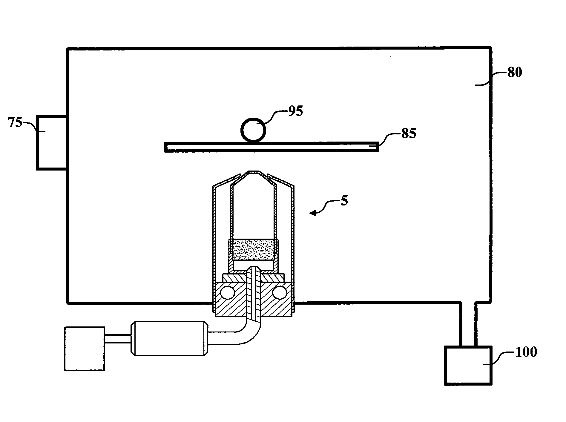
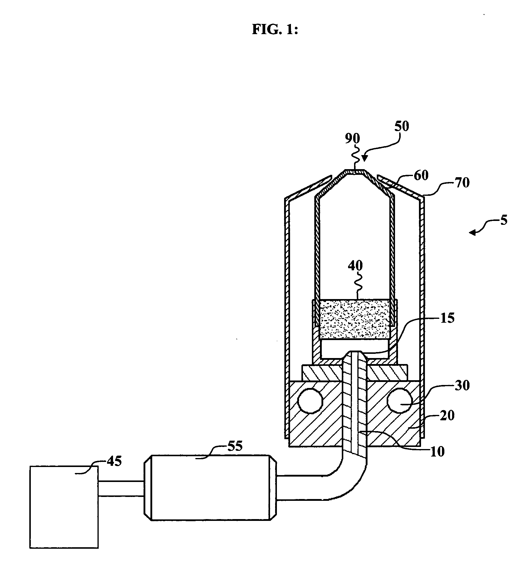
[0029] Turning now to FIG. 1, there is shown a cross sectional view of one embodiment of a device of this disclosure. Vaporization apparatus 5 is a device for vaporizing organic materials onto a substrate surface to form a film and includes a permeable first member 40, a manifold 60, and a metering means, by which we mean a means for fluidizing powdered organic material or providing organic material in a fluidized powdered form, metering the powdered organic material and directing a stream of such fluidized powder onto permeable first member 40. Permeable first member 40 can be part of manifold 60. Manifold 60 also includes one or more apertures 90. Vaporization apparatus 5 also includes one or more shields 70.

[0030] In one embodiment, container 45 is a container for receiving a quantity of organic material in powdered form. Metering valve 55 in this embodiment includes a means for fluidizing the organic material and metering the fluidized powdered organic material at a controlled ...


PUM

PropertyMeasurementUnit
Temperatureaaaaaaaaaa

Abstract

A method for vaporizing organic materials onto a surface, to form a film includes providing a quantity of organic material in a fluidized powdered form; metering the powdered organic material and directing a stream of such fluidized powder onto a first member; heating the first member so that as the stream of fluidized powder is vaporized; collecting the vaporized organic material in a manifold; and providing a second member formed with at least one aperture in communication with the manifold that permits the vaporized organic material to be directed onto the surface to form a film.

Description

CROSS REFERENCE TO RELATED APPLICATIONS [0001] Reference is made to commonly assigned U.S. patent application Ser. No. 10 / 352,558 filed Jan. 28, 2003 by Jeremy M. Grace et al., entitled “Method of Designing a Thermal Physical Vapor Deposition System”, U.S. patent application Ser. No. 10 / 784,585 filed Feb. 23, 2004, by Michael Long et al, entitled “Device and Method for Vaporizing Temperature Sensitive Materials”, U.S. patent application Ser. No. ______ filed concurrently herewith, by Michael Long et al, entitled “High Thickness Uniformity Vaporization Source”, the disclosures of which are herein incorporated by reference.FIELD OF THE INVENTION [0002] The present invention relates to the field of physical vapor deposition where a source material is heated to a temperature so as to cause vaporization and create a vapor plume to form a thin film on a surface of a substrate. BACKGROUND OF THE INVENTION [0003] An organic light emitting diode (OLED) device includes a substrate, an anode, ...

Claims


Application Information

Patent Timeline
IPC IPC(8): C23C14/12C23C14/24
CPCC23C14/12Y10S427/101C23C14/246C23C14/228C23C14/00
Inventor LONG, MICHAELSTRIP, DAVID R.GRACE, JEREMY M.FREEMAN, DENNIS R.REDDEN, NEIL P.KOPPE, BRUCE E.
Owner GLOBAL OLED TECH
Why Eureka
Try Eureka