Deposition system using sealed replenishment container

a replenishment container and replenishment system technology, applied in the direction of vacuum evaporation coating, chemical vapor deposition coating, coating, etc., can solve the problems of significant degradation, changes in the structure of the molecules and associated changes in the material properties, and the use of organic materials in the manufacture of oled devices are often subject to degradation, so as to reduce the risk of degrading, the effect of steady vaporization rate and linear vaporization rate control

Active Publication Date: 2007-05-10
GLOBAL OLED TECH
View PDF9 Cites 27 Cited by
  • Summary
  • Abstract
  • Description
  • Claims
  • Application Information

AI Technical Summary

Benefits of technology

[0022] It is an advantage of the present invention that the continuous heating of material during operation of prior art devices is eliminated in that only a small portion of particulate material is heated, for a short period of time and at a controlled rate. The bulk of particulate material is maintained at a temperature that can be as much as 300° C. cooler than the desired rate-dependent vaporization temperature. This can be particularly advantageous when vaporizing organic materials.
[0023] It is a further advantage of the present invention that it can maintain a steady vaporization rate with a continuously replenished charge of particulate material and with a steady heater temperature. The device thus allows extended operation of the source with substantially reduced risk of degrading even highly temperature-sensitive organic materials.
[0024] It is a further advantage of the present invention that it permits materials having different vaporization rates and degradation temperature thresholds to be co-sublimated in the same source.
[0025] It is a further advantage of the present invention that it permits linear vaporization rate control by controlling the volumetric metering rate or controlling the feed pressure of the compacted particulate material.
[0026] It is a further advantage of the present invention that it can rapidly stop and reinitiate vaporization and achieve a steady vaporization rate quickly by controlling the metering rate of the particulate material, reducing contamination of the deposition chamber walls and conserving the particulate materials when a substrate is not being coated.
[0027] It is a further advantage that the present device achieves substantially higher vaporization rates than in prior art devices with substantially reduced material degradation. Further still, no heater temperature change is required as the source material is consumed.

Problems solved by technology

The organic materials used in the manufacture of OLED devices are often subject to degradation when maintained at or near the desired rate dependant vaporization temperature for extended periods of time.
Exposure of sensitive organic materials to higher temperatures can cause changes in the structure of the molecules and associated changes in material properties.
In this manner, the material is consumed before it has reached the temperature exposure threshold to cause significant degradation.
The limitations with this practice are that the available vaporization rate is very low due to the limitation on heater temperature, and the operation time of the source is very short due to the small quantity of material present in the source.
The low deposition rate and the frequent and time consuming process associated with recharging a source has placed substantial limitations on the throughput of OLED manufacturing facilities.
A secondary consequence of heating the entire organic material charge to roughly the same temperature is that it is impractical to mix additional organic materials, such as dopants, with a host material unless the vaporization behavior and vapor pressure of the dopant is very close to that of the host material.
This is generally not the case and, as a result, prior art devices frequently require the use of separate sources to co-deposit host and dopant materials.
This restriction has imposed a substantial limitation on the architecture of OLED devices, increases the necessary size and cost of the vacuum deposition chamber and decreases the reliability of the system.
Among the acknowledged problems of conventional approaches to vapor deposition are material purity and the difficulty in maintaining a continuous fabrication sequence that would allow deposition apparatus to operate for extended periods of time, without costly down-time for cleaning, for replenishment or recharging of material, and for pre-heating.
Both of these problems present significant constraints on deposition system design.
However, the solution proposed in the '5857 Chow et al. disclosure is not advantaged for any type of continuous processing because this batch replenishment process still requires a pre-heating period during which material in the deposition chamber heats up to deposition temperature.
While this type of solution can help to improve overall material purity, however, it still requires that the deposition process be stopped in order to allow replenishment, then restarted again once the sealed source is placed into position, the seal broken, and the material heated to deposition temperatures.
Thus, it can be seen that while solutions such as those proposed in the '5857 Chow et al. and '9914 Yamazaki et al. disclosures may serve to improve material purity to some degree and even minimize bake-out pre-treatment requirements, these solutions do not wholly eliminate the pre-heating cycle.
However, because some amount of pre-heating or bake-out time is required with conventional techniques, both materials must be substantially of the same sublimation temperature (to within a small tolerance in the range of no more than about ±20 degrees C. difference).
Where materials differ in vaporization temperature by more than a few degrees, conditions for pre-heating or bake-out may not be optimal.

Method used


Image

  • Deposition system using sealed replenishment container
  • Deposition system using sealed replenishment container
  • Deposition system using sealed replenishment container

Examples


Embodiment Construction

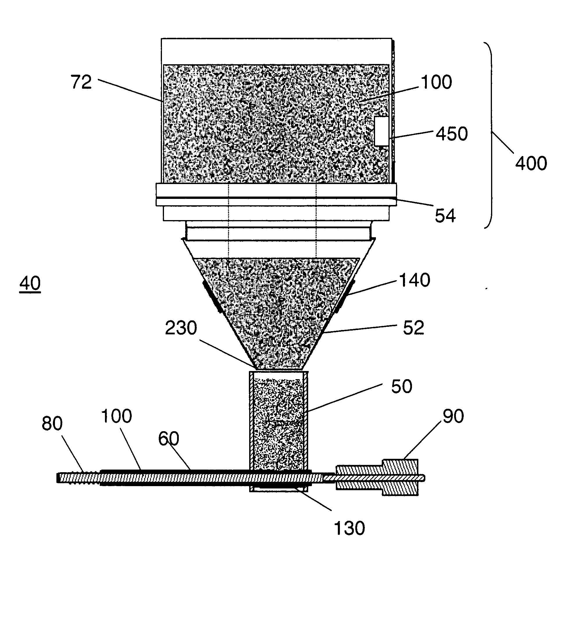
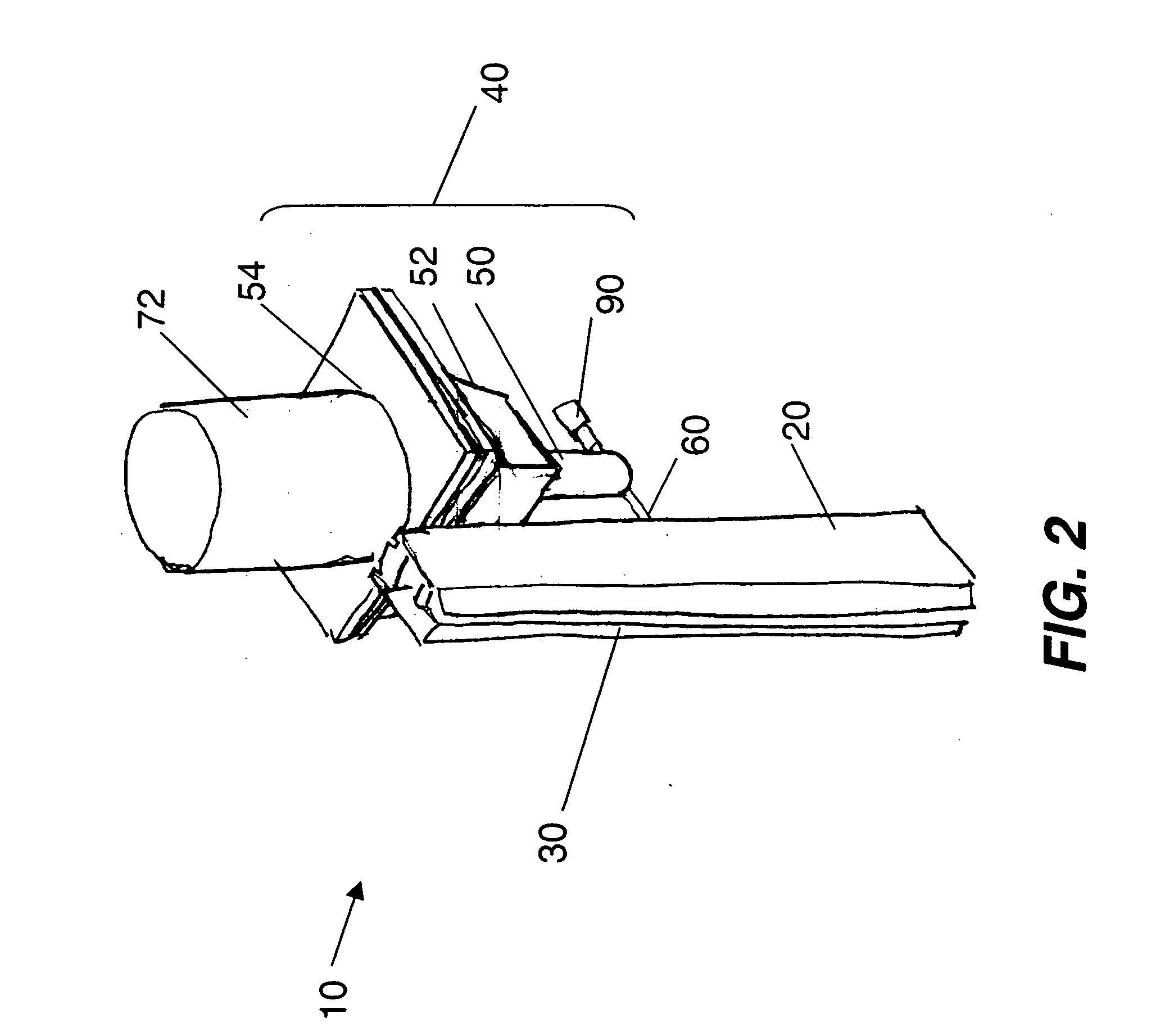
[0052] Turning now to FIG. 2, there is shown a three-dimensional view of one embodiment of an apparatus according to the present invention for vaporizing organic particulate materials and condensing them onto a surface to form a layer. A vaporization apparatus 10 includes a manifold 20 and an attached feeding apparatus 40. Feeding apparatus 40 includes a feed container 50 and a feeding path 60. Feed container 50 is provided with a quantity of organic or other material in a particulate form, such as a powder in one embodiment.

[0053] Manifold 20 includes one or more apertures 30 through which vaporized organic material can exit to a substrate surface. Manifold 20 is shown in an orientation whereby it can form a layer on a vertically-oriented substrate, but it is not limited to this orientation. For example, manifold 20 can be oriented horizontally and can form a layer on a horizontal substrate. Manifold 20 has been described in detail by Long et al. in commonly-assigned, above-cited ...


PUM

PropertyMeasurementUnit
temperatureaaaaaaaaaa
volumeaaaaaaaaaa
heightaaaaaaaaaa

Abstract

A method for vaporizing particulate material and depositing it onto a surface to form a layer, includes providing a supply of particulate material in a replenishment container, the replenishment container having a sealed interface fitting; mounting the replenishment container to a supply hopper defining at least one feed opening, and breaking the seal at the interface fitting; transferring particulate material from the replenishment container to the supply hopper; and transferring such particulate material through the feed opening along a feeding path to a vaporization zone where at least a component portion of the particulate material is vaporized and delivered to the surface to form the layer.

Description

CROSS REFERENCE TO RELATED APPLICATIONS [0001] Reference is made to commonly assigned U.S. patent application Ser. No. 10 / 805,980 filed Mar. 22, 2004 entitled “Vaporizing Fluidized Organic Materials” by Long et al.; U.S. patent application Ser. No. 10 / 784,585 filed Feb. 23, 2004, entitled “Device and Method for Vaporizing Temperature Sensitive Materials” by Long et al.; U.S. patent application Ser. No. 10 / 945,940, filed Sep. 21, 2004, entitled “Delivering Organic Power to a Vaporization Zone” by Long et al; U.S. patent application Ser. No. 11 / 134,654 filed May 20, 2005, entitled “Delivering Particulate Material to a Vaporization Zone” by Long et al; U.S. patent application Ser. No. 10 / 945,941 filed Sep. 21, 2004 entitled “Delivering Organic Powder to a Vaporization Zone” by Long et al.; U.S. patent application Ser. No. 11 / 134,139 filed May 20, 2005, entitled “Delivering Particulate Material to a Vaporization Zone” by Long et al and U.S. patent application Ser. No. ______ filed concu...

Claims


Application Information

Patent Timeline
Patent Type & Authority Applications(United States)
IPC IPC(8): C23C16/00B05D3/00B05D3/12
CPCC23C14/12C23C14/246H01L51/001H01L51/56H10K71/164H10K71/00
Inventor BOROSON, MICHAEL L.BRANDT, E. STEVEN
Owner GLOBAL OLED TECH
Why Eureka
Try Eureka