Metering material to promote rapid vaporization

a technology of metering material and rapid vaporization, which is applied in the direction of vacuum evaporation coating, chemical vapor deposition coating, coating, etc., can solve the problems of significant degradation, changes in the structure of the molecule and associated changes in the material properties, and the use of organic materials in the manufacture of oled devices are often subject to degradation, so as to achieve stable vaporization rate and reduce the risk of degradation , the effect of allowing linear vaporization ra

Active Publication Date: 2006-11-09
GLOBAL OLED TECH
View PDF11 Cites 2 Cited by
  • Summary
  • Abstract
  • Description
  • Claims
  • Application Information

AI Technical Summary

Benefits of technology

[0015] It is an advantage of the present invention that it overcomes the heating and volume limitations of prior art devices in that material is continuously dispensed into a source such that only a small portion of organic material is heated to the desired rate-dependant vaporization temperature, for a short period of time and at a controlled rate. The bulk of organic material is maintained at a temperature that is as much as 300° C. cooler than the vaporization temperature. It is therefore a feature of the present invention to maintain a steady vaporization rate with a continuously replenished accurately metered charge of material and with a steady heater temperature. The invention permits extended operation of the apparatus with substantially reduced risk of degrading even very temperature-sensitive organic materials. This feature additionally permits materials having different vaporization rates and degradation temperature thresholds to be co-vaporized.
[0016] It is a further advantage of the present invention that it permits linear vaporization rate control by controlling the volumetric metering rate of the compacted organic material powder.
[0017] It is a further advantage of the present invention that it can rapidly stop and reinitiate vaporization and achieve a steady vaporization rate quickly by controlling the metering rate of the organic material. This feature minimizes contamination of the deposition chamber walls and conserves the organic materials when a substrate is not being coated.
[0018] It is a further advantage that the present device achieves substantially higher vaporization rates than in prior art devices with substantially reduced material degradation. Further still, no heater temperature change is required as the source material is consumed.
[0019] It is a further advantage of the present invention that it can provide a vapor source in any orientation, which is not possible with prior-art devices.

Problems solved by technology

The organic materials used in the 30 manufacture of OLED devices are often subject to degradation when maintained at or near the desired rate-dependent vaporization temperature for extended periods of time.
Exposure of sensitive organic materials to higher temperatures can cause changes in the structure of the molecules and associated changes in material properties.
In this manner, the material is consumed before it has reached the temperature exposure threshold to cause significant degradation.
The limitations with this practice are that the available vaporization rate is very low due to the limitation on heater temperature, and the operation time of the source is very short due to the small quantity of material present in the source.
The low deposition rate and the frequent and time consuming process associated with recharging a source has placed substantial limitations on the throughput of OLED manufacturing facilities.
A secondary consequence of heating the entire organic material charge to roughly the same temperature is that it is impractical to mix additional organic materials, such as dopants, with a host material unless the vaporization behavior and vapor pressure of the dopant is very close to that of the host material.
This is generally not the case and as a result, prior art devices frequently require the use of separate sources to co-deposit host and dopant materials.
This restriction has imposed a substantial limitation on the architecture of OLED devices, increases the necessary size and cost of the vacuum deposition chamber and decreases the reliability of the system.
This gradient co-deposition is unavoidable in prior art sources where a single material is vaporized from each of multiple sources.
A further limitation of prior art sources is that the geometry of the interior of the vapor manifold changes as the organic material charge is consumed.

Method used


Image

  • Metering material to promote rapid vaporization
  • Metering material to promote rapid vaporization
  • Metering material to promote rapid vaporization

Examples


Embodiment Construction

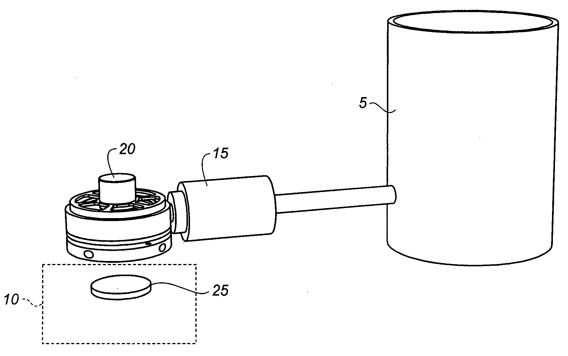
[0023] Turning now to FIG. 1, a container 5 is provided and holds a powdered or granular material. This material may be a single component or in alternative embodiments it may contain multiple components. The material can be powdered or granular. The container 5 can be provided with a structure for agitating or fluidizing the material (not visible in figure). There are many well known ways for providing this functionality; the use of a horizontal auger is particularly common. Alternatively, the container 5 may be vibrated by actuators attached to the walls of the container 5. A vaporization zone 10 is provided in a manner that is thermally isolated from the container 5 which contains the powdered or granular material. By thermally isolating the vaporization zone 10 from the container 5, the contents of the container 5 are protected from an elevation in temperature which may lead to degradation. The embodiment in FIG. 1 uses distance to achieve thermal isolation. However, other ways ...


PUM

PropertyMeasurementUnit
temperatureaaaaaaaaaa
forcesaaaaaaaaaa
Temperatureaaaaaaaaaa

Abstract

Apparatus for vaporization of powdered or granular material, includes a container for holding powdered or granular material having at least one component; a vaporization structure; and a positive displacement mechanism spaced from the vaporization structure defining a chamber for receiving powdered or granular material from the container, and delivering such powdered or granular material to the vaporization structure, the positive displacement mechanism defining an orifice for delivering powdered or granular material from the chamber to the vaporization structure, an actuable member movable in first and section directions into the orifice and back from the orifice to be spaced therefrom for driving powdered or granular material from the chamber through the orifice for delivery to the vaporization structure and a vibratory diaphragm for fluidized material in the chamber between the actuable member and the orifice.

Description

CROSS REFERENCE TO RELATED APPLICATIONS [0001] Reference is made to commonly assigned U.S. patent application Ser. No. 10 / 784,585 filed Feb. 23, 2004 by Michael Long et al, entitled “Device and Method for Vaporizing Temperature Sensitive Materials”, U.S. patent application Ser. No. 10 / 945,941 filed Sep. 21, 2004 by Michael Long et al, entitled “Delivering Organic Powder to a Vaporization Zone”, U.S. patent application Ser. No. 11 / 050,934 filed Feb. 4, 2005, by Michael Long et al, entitled “Feeding Organic Material to a Heated Surface”, U.S. patent application Ser. No. ______ filed concurrently herewith, by Michael Long et al, entitled “Controllably Feeding Powdered Or Granular Material” the disclosures of which are herein incorporated by reference.FIELD OF THE INVENTION [0002] The present invention relates to the field of physical vapor deposition where material is heated to a temperature causing rapid vaporization, and create a vapor plume that condenses to form a thin film on a su...

Claims


Application Information

Patent Timeline
Patent Type & Authority Applications(United States)
IPC IPC(8): C23C16/00
CPCC23C14/12C23C14/24H01L51/001H01L51/0008C23C14/246H10K71/16H10K71/164
Inventor LONG, MICHAEL
Owner GLOBAL OLED TECH
Why Eureka
Try Eureka