Purifying organic materials for physical vapor deposition

a technology of organic materials and physical vapor deposition, which is applied in the direction of vacuum evaporation coating, chemical vapor deposition coating, coating, etc., can solve the problems of difficult to provide and maintain organic materials in a relatively high purity state, changes in the structure of molecules, and associated changes in material properties, so as to improve device performance, reduce contamination, and steady vaporization rate

Active Publication Date: 2007-05-10
GLOBAL OLED TECH
View PDF12 Cites 5 Cited by
  • Summary
  • Abstract
  • Description
  • Claims
  • Application Information

AI Technical Summary

Benefits of technology

[0020] It is an advantage of the present invention that it improves device performance through decrease in contamination from absorbed gases and other highly volatile contaminants.
[0021] It is a further advantage of the present invention that it allows for continuous coating operation without the need to stop for chamber venting, material loading, chamber evacuation, or outgassing material steps.
[0022] It is a further advantage of the present invention that the continuous heating of material during operation of prior art devices is eliminated in that only a small portion of organic material is heated, for a short period of time and at a controlled rate. The bulk of organic material is maintained at a temperature that can be as much as 300° C. cooler than the desired rate-dependent vaporization temperature.
[0023] It is a further advantage of the present invention that it can maintain a steady vaporization rate with a continuously replenished charge of organic material and with a steady heater temperature. The device thus allows extended operation of the source with substantially reduced risk of degrading even very temperature-sensitive organic materials.
[0024] It is a further advantage of the present invention that it permits materials having different vaporization rates and degradation temperature thresholds to be co-sublimed in the same source, reducing the number of sources and controllers, and reducing the volume of the coating chamber.
[0025] It is a further advantage of this invention that it can remove adsorbed gases or contaminants from the organic materials to be vaporized through the device.

Problems solved by technology

It is known that providing and maintaining the organic materials in a state of relatively high purity is difficult.
The organic materials used in the manufacture of OLED devices are often subject to degradation when maintained at or near the desired rate dependent vaporization temperature for extended periods of time.
Exposure of sensitive organic materials to higher temperatures can cause changes in the structure of the molecules and associated changes in material properties.
In this manner, the material is consumed before it has reached the temperature exposure threshold to cause significant degradation.
The limitations with this practice are that the available vaporization rate is very low due to the limitation on heater temperature, and the operation time of the source is very short due to the small quantity of material present in the source.
The low deposition rate and the frequent and time consuming process associated with recharging a source has placed substantial limitations on the throughput of OLED manufacturing facilities.
A secondary consequence of heating the entire organic material charge to roughly the same temperature is that it is impractical to mix additional organic materials, such as dopants, with a host material unless the vaporization behavior and vapor pressure of the dopant is very close to that of the host material.
This is generally not the case and as a result, prior art devices frequently require the use of separate sources to co-deposit host and dopant materials.
In practice, the number of such sources used to co-deposit different materials has been limited to three.
This restriction has imposed a substantial limitation on the architecture of OLED devices.
The requirement of many single component sources increases the necessary size and cost of the vacuum deposition chamber, increases the number of independent power supplies required to control the sources, and decreases the reliability of the system.
This gradient co-deposition is unavoidable in prior art sources where a single material is vaporized from each of multiple sources.
A further limitation of prior art sources is that the geometry of the vapor manifold changes as the organic material charge is consumed, which requires that the heater temperature change to maintain a constant vaporization rate for a given organic material.
An OLED, having multiple organic layers, can become inoperative if such layers include particles or particulates.
Further, the aforementioned aspects of organic powders, flakes, or granules can lead to non-uniform heating of such organic materials in physical vapor deposition sources, causing spatially non-uniform vaporization of organic material.
This can result in non-uniform layers on an OLED device.
Moreover, undesired contaminants can be vapor-deposited on a structure.

Method used


Image

  • Purifying organic materials for physical vapor deposition
  • Purifying organic materials for physical vapor deposition
  • Purifying organic materials for physical vapor deposition

Examples


Embodiment Construction

[0041] The organic layers of an OLED display include at least one organic or organo-metallic material that produces light, known as electroluminescence (EL), as a result of electron-hole recombination in the layer. Hereinafter, the term “organic” will be taken to include both purely organic as well as organo-metallic materials.

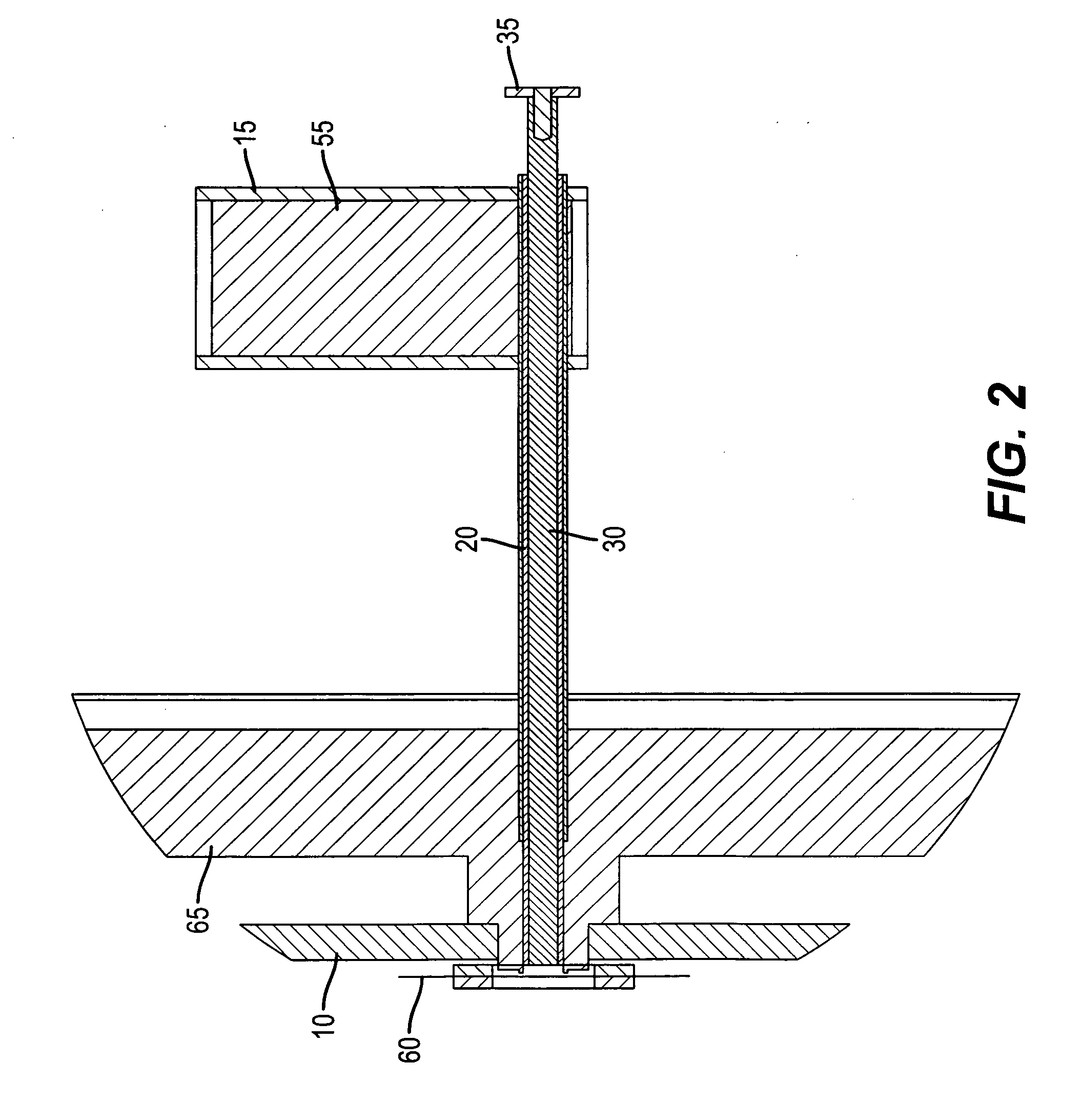
[0042] Turning now to FIG. 2, there is shown a cross-sectional view of one embodiment of a portion of an apparatus for feeding and evaporating powdered organic materials comprising multiple components. Such an apparatus is a thermal physical vapor deposition source and has been described by Long et al. in above-cited U.S. patent application Ser. Nos. 10 / 945,940 and 11 / 134,654. An auger structure 30 moves organic material 55 from a feed vessel 15 along a feeding path 20 into a manifold 10 and a heating element 60, which can be e.g. a heated screen. A base 65 is a heat-dissipating structure to prevent much of the heat from heating element 60 from traversing the...


PUM

PropertyMeasurementUnit
temperaturesaaaaaaaaaa
temperatureaaaaaaaaaa

Abstract

A method for evaporating a plurality of purified organic materials in a thermal physical vapor deposition system, comprising the steps of: mixing predetermined amounts of first and second organic materials to form a mixture of materials at a predetermined ratio; processing at least one of the organic materials at less than the sublimation temperature of the at least one of the organic materials before or after mixing to remove a first contaminant, wherein if processing is after mixing, the processing temperature is lower than the sublimation temperature of each of the organic materials; providing a thermal physical vapor deposition source; transferring the purified mixture of organic materials into the thermal physical vapor deposition source while maintaining the purified mixture of organic materials in a controlled, contaminant-free environment; and using the source to evaporate the purified mixture of organic materials.

Description

CROSS REFERENCE TO RELATED APPLICATIONS [0001] Reference is made to commonly assigned U.S. patent application Ser. No. 10 / 663,636 filed Sep. 19, 2003, entitled “Forming Homogeneous Mixtures of Organic Materials for Physical Vapor Deposition Using Melting” by Carlton et al; U.S. patent application Ser. No. 10 / 945,940 filed Sep. 21, 2004, entitled “Delivering Organic Powder to a Vaporization Zone” by Long et al; U.S. patent application Ser. No. 11 / 050,924 filed Feb. 4, 2005, entitled “Controllably Feeding Organic Material in Making OLEDS” by Long et al; U.S. patent application Ser. No. 11 / 134,654 filed May 20, 2005 entitled “Delivering Particulate Material to a Vaporization Zone” by Long et al; the disclosures of which are incorporated herein by reference. FIELD OF THE INVENTION [0002] The present invention relates to the field of physical vapor deposition of OLED materials, and more specifically to purifying the materials for use in a physical vapor deposition apparatus. BACKGROUND O...

Claims


Application Information

Patent Timeline
Patent Type & Authority Applications(United States)
IPC IPC(8): C23C16/00B05D3/06
CPCC23C14/12C23C14/246C23C14/564
Inventor BOROSON, MICHAEL L.COK, RONALD S.LONG, MICHAELFREEMAN, DENNIS R.GRACE, JEREMY M.
Owner GLOBAL OLED TECH
Why Eureka
Try Eureka