
Method for controlling a hydraulic piston/cylinder unit

a hydraulic piston and cylinder technology, applied in the direction of fluid couplings, gearings, servomotors, etc., can solve the problems of insufficient security of working operations, difficult in practice, and failure to detect the end of a working operation, so as to avoid unnecessary idle times, fast detection of the end position, and the effect of pressure build-up in the hydraulic lin

Inactive Publication Date: 2005-09-29
WAGNER VERMOGENSVERWALTUNGS GMBH & CO KG
View PDF1 Cites 22 Cited by
  • Summary
  • Abstract
  • Description
  • Claims
  • Application Information

AI Technical Summary

Benefits of technology

[0005] The method of the present invention allows for an automatic stop of the working operation due to the detection of the condition that the hydraulic pressure in a working stroke cannot rise further. The predetermined limit value is either zero or a value close to zero. The pressure source is set to a predetermined terminal value selected corresponding to the desired terminal force. The condition that the piston-cylinder unit generates this force is detected by the fact that a further pressure increase is not possible because of the pressure limit of the pressure source so that in the subsequent interval the pressure increase is less than zero or another limit value. Thus, the reaching of the aim of the working operation can be detected readily and fully automatically.
[0008] The invention allows to detect the operational condition of the piston-cylinder unit by detecting the pressure in the pressure line and by forming the pressure gradient over time, without requiring end switches or other auxiliary means. It is another advantage that all pressure measurements may be made at the pressure source or the pressure generating aggregate, respectively, and that no measuring means have to be provided at the piston-cylinder unit. The maximum load on the components is reached at the end of the working operation and maintained only for a short time until it is detected that the terminal pressure has been reached and no further pressure increase occurs. This detection is usually terminated within a few milliseconds.
[0011] This aspect of the invention is based on the idea that upon reaching the piston end position, the pressure build-up in the hydraulic line quickens. This is due to the fact that the cylinder space does no longer increase and the pressure source then operates against a blocking. The increase in the pressure gradient over time is detected and used as a criterion for reaching the end position. This allows for a very fast detection of the end position. In particular, it is also prevented that upon reaching the piston end position the pressure is increased beyond the necessary amount. Thus, a very fast switching to the return stroke is effected so that unnecessary idle times are avoided and no unnecessary material stresses occur.

Problems solved by technology

Generally, there is a problem to detect when the working operation is terminated and the piston-cylinder unit should be retracted or left in its position.
Detecting the end of a working operation, where a defined force has been exerted on a load, is difficult in practice.
This is disadvantageous.
The working operation is not sufficiently secure, i.e. reaching the desired torque is not guaranteed.
Neither is the working operation performed in minimum time, but it may happen that after the end of a working operation another working stroke is attempted.
Further, the user must continuously be alert, resulting in high personnel costs.

Method used


Image

  • Method for controlling a hydraulic piston/cylinder unit
  • Method for controlling a hydraulic piston/cylinder unit

Examples


Embodiment Construction

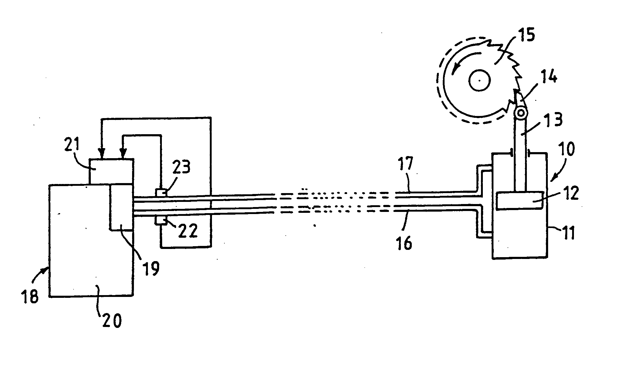
[0018] The embodiment of the invention described below is a hydraulic power wrench serving to tighten screws, wherein a desired terminal torque is reached. Such a power wrench includes a hydraulic piston-cylinder unit 10 with a cylinder 11 and a piston 12 movable within the cylinder. The piston 12 is connected to a piston rod 13. A ratchet lever 14 is provided at the end of the piston rod 13, engaging the toothing of a ratchet wheel 15. The reciprocating movement of the piston rod 13 intermittently turns the ratchet wheel 15 in the direction of the arrow. The ratchet wheel 15 is coupled to a socket wrench (not illustrated) that is set on the screw head to be turned. The screw is turned by the reciprocating movement of the piston 12.

[0019] Hydraulic lines 16, 17 connect the two cylinder spaces of the cylinder 11 to a hydraulic pressure aggregate 18 including a switching valve 19. By means of the switching valve 19, each of the hydraulic lines 16, 17 can alternately connected to a pr...


PUM


Abstract

The control of the pressure supply to a piston-cylinder unit (10) is effected by monitoring the pressure in the corresponding line (16) through a pressure sensor (22). This pressure is measured in fixed time intervals and the changes in pressure are determined. When the change in pressure has become zero, it is detected that the set terminal pressure has been reached so that the working operation is ended. A switching to the return stroke is effected when the pressure increase in at least one time interval is greater than in at least one of the previous intervals of the working operation. The control is independent from the type of piston-cylinder unit employed and requires no sensors at the piston-cylinder unit.

Description

BACKGROUND OF THE INVENTION [0001] The invention refers to a method of controlling the pressure supply of a hydraulic piston-cylinder unit connected to a pressure source, which performs a working operation comprising alternating working strokes and return strokes, as well as to a hydraulic drive means for controlling a piston-cylinder unit. [0002] Piston-cylinder units are often used to perform a working operation with repeated working strokes and return strokes. For example, such an application is found in power wrenches where a ratchet wheel is rotated by a piston-cylinder unit through a detent that turns the ratchet wheel further on by one angular segment each time. Generally, there is a problem to detect when the working operation is terminated and the piston-cylinder unit should be retracted or left in its position. Detecting the end of a working operation, where a defined force has been exerted on a load, is difficult in practice. In general, this detection is made by an opera...

Claims


Application Information

Patent Timeline
Patent Type & Authority Applications(United States)
IPC IPC(8): F15B11/08B25B21/00B25B23/145F15B11/15F15B15/06F16H25/20
CPCB25B21/005B25B23/145F16H25/2015F15B11/15F15B15/061B25B23/1456
Inventor WAGNER, PAUL-HEINZ
Owner WAGNER VERMOGENSVERWALTUNGS GMBH & CO KG
Learn More