Lubricants in cutting tools for dry machining

a technology of lubricants and cutting tools, applied in the field of cutting tools, can solve the problems of limited source of lubricating materials, and achieve the effects of reducing vibration, reducing power consumption, and reducing nois

Inactive Publication Date: 2005-09-29
GENERAL MOTORS COMPANY
View PDF12 Cites 13 Cited by
  • Summary
  • Abstract
  • Description
  • Claims
  • Application Information

AI Technical Summary

Benefits of technology

[0010] Tests have been conducted comparing an unfilled drill with a dry lubricant filled drill for boring holes in an aluminum alloy workpiece. The dry lubricant filled drill operated with lower power consumption, lower vibration, lower noise, and per

Problems solved by technology

The source of such lubrication material is limited to th

Method used


Image

  • Lubricants in cutting tools for dry machining
  • Lubricants in cutting tools for dry machining

Examples


Embodiment Construction

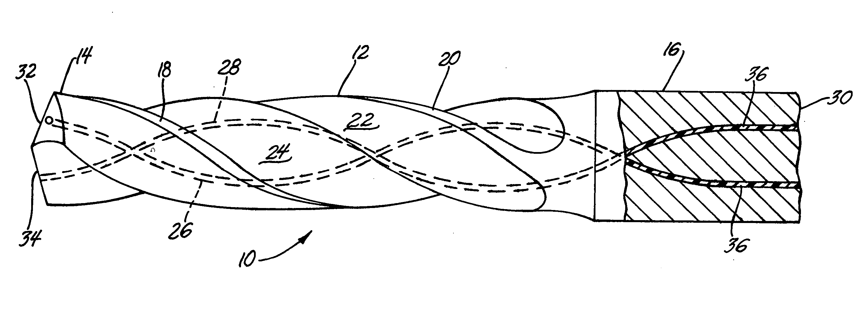
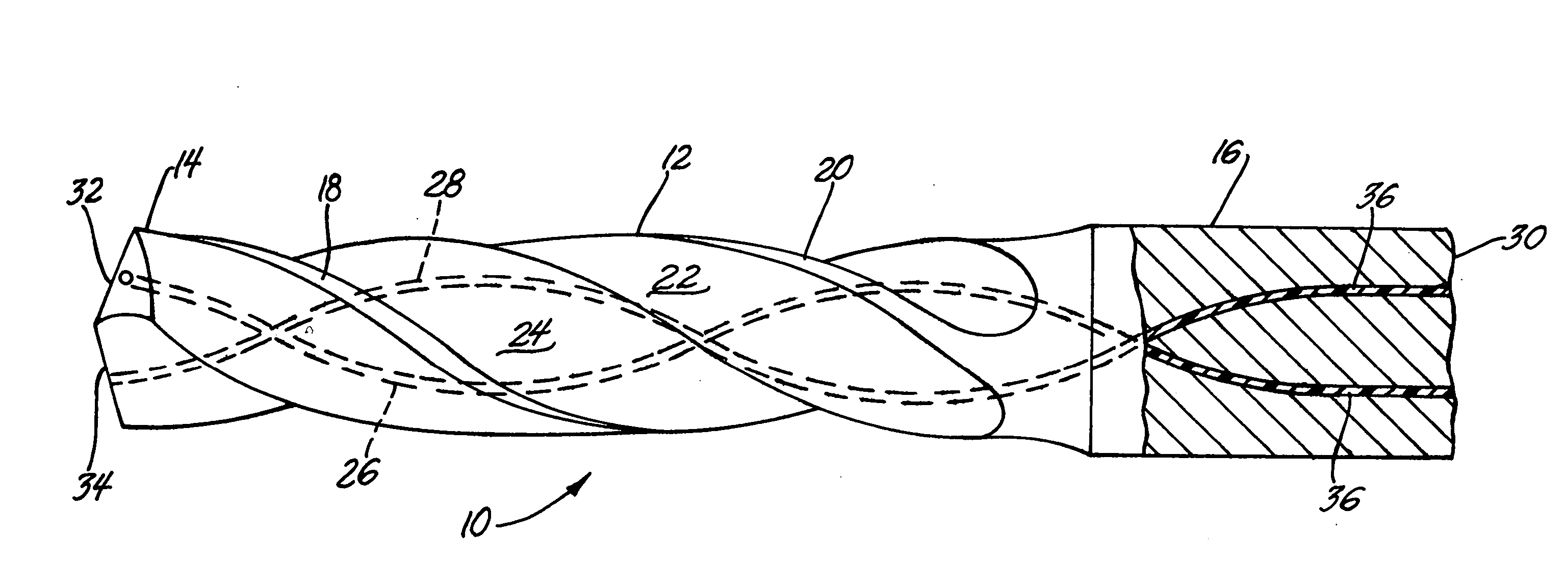
[0013] Cutting tools are usually formed from a round bar of metal having a length and diameter specified by the intended application. In the drawing FIGURE, drill 10 is constructed of a body section 12, a cutting head end 14 and a mounting end 16. A collet, not shown, may be attached to the mounting end 16 for securing of the drill 10 in a suitable toolholder. In this example, drill 10 has helical twist lands 18 and 20. Helical twist longitudinal flutes 22 and 24 are cut between lands 18 and 20 and provide channels for chip removal during a cutting operation. Also, in this example, body section 12 and cutting head end 14 are formed of the same material so there is not a definite interface between them. Lands 18 and 20 and flutes 22 and 24 extend from cutting head end 14 along body section 12 and terminate at mounting end 16. In some cutting tool embodiments the body and mounting portions of the tool may be made, for example, of tool steel while the cutting head is made of a harder m...


PUM

PropertyMeasurementUnit
Percent by massaaaaaaaaaa
Weightaaaaaaaaaa
Lengthaaaaaaaaaa

Abstract

Workpiece cutting tools, such as drills, are often provided with through holes that preferably extend from the cutting end of the tool along its length to the holding end. In accordance with this invention, such through holes of a cutting tool are filled with a lubricating oil-in a thermoplastic polymer matrix by injection or molding of the mixture into the holes. In the operation of the tool, the oil thus stored within the tool flows in the polymer matrix to the cutting site to reduce cutting power requirements and wear of the tool. Through the use of such cutting tools, the use of metal removal fluids can be eliminated and dry machining facilitated.

Description

TECHNICAL FIELD [0001] This invention pertains to cutting tools, such as drills, containing a dry lubricant. More specifically, this invention pertains to cutting tools with through holes containing an oil-filled polymer lubricant for delivery of lubricating oil to the cutting site during machining operation. BACKGROUND OF THE INVENTION [0002] Cutting tools, such as drills, reamers, taps and boring bars, are widely used in metal removal (machining) operations for making articles of manufacture. In sophisticated manufacturing operations, such as in machining centers using computer numerical controls, the cutting tool is clamped in a toolholder which in turn is secured in the spindle of a machine tool. The machine tool locates and powers the cutting tool against a workpiece for the cutting operation. Usually, a lubricating and cooling fluid, known as a metal removal fluid (MRF), is applied through nozzles onto the part being machined in a flood application. In situations where the MRF...

Claims


Application Information

Patent Timeline
IPC IPC(8): B23B51/06C10M107/04
CPCB23B51/06B23B2270/54C10M107/04Y10T408/455C10N2240/401C10N2250/18C10M2205/022C10N2040/22C10N2050/14
Inventor DASCH, JEAN M.
Owner GENERAL MOTORS COMPANY
Why Eureka
Try Eureka