Method of generating writing pattern data of mask and method of writing mask

a mask and writing pattern technology, applied in the field of writing technique of masks, can solve the problems of in-plane displacement, image shift of projected/reduced pattern on the wafer, positional shift by elastic deformation of the mask also raises a problem, and achieve the effect of reducing the ratio of the projection optics of the exposure tool

Active Publication Date: 2005-09-29
KIOXIA CORP
View PDF9 Cites 36 Cited by
  • Summary
  • Abstract
  • Description
  • Claims
  • Application Information

AI Technical Summary

Problems solved by technology

In the projection optics of the reflective type exposure system, since a non-telecentric system is constituted on a mask side, image shift of the projected / reduced pattern on the wafer, which is in-plane displacement, is a problem.
In the same manner as in a usual photo-mask, a positional shift by elastic deformation of the mask also raises a problem.
Since a film structure of the EUV mask is complicated, there is a possibility that the pattern positional shift by in-plane stress non-uniformity of the film raises a problem.
Displacement of the mask plane (or height) in the Z-direction (vertical direction), which is a cause for the image shift, is caused not only by an uneven shape (e.g., uneven surface) of the mask but also flatness of a mask holding mechanism (mask chuck).
This also applies to unevenness of the wafer, or flatness of the wafer chuck.
Furthermore, mechanical fluctuation in the Z-direction in driving the mask or a wafer stage is also a cause.
Thus, since the image shift is attributed to a mask front surface shape at exposure, and does not indicate a constant value, it is difficult to control the shift by the exposure tool.
Therefore, even when the distance between the mask and the wafer surface is controlled to be constant based on the average vertical position in the irradiation region plane, image shifts are produced in individual patterns in accordance with the local unevenness included in the irradiation region plane, and therefore positional precision is deteriorated.
As described above, there has been a problem that a transfer pattern cannot be obtained with sufficient positional precision in a non-telecentric exposure system represented by the EUV lithography technique.

Method used


Image

  • Method of generating writing pattern data of mask and method of writing mask
  • Method of generating writing pattern data of mask and method of writing mask
  • Method of generating writing pattern data of mask and method of writing mask

Examples


first embodiment

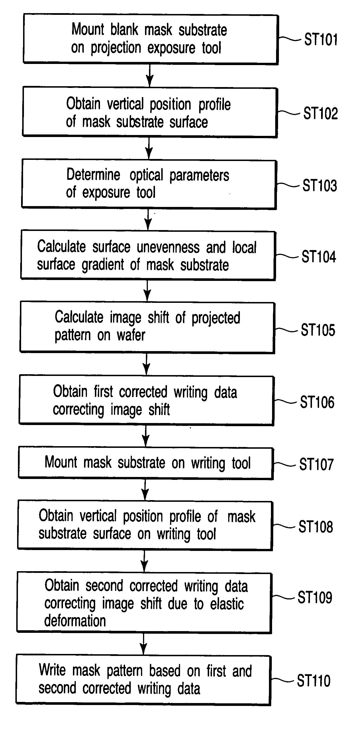
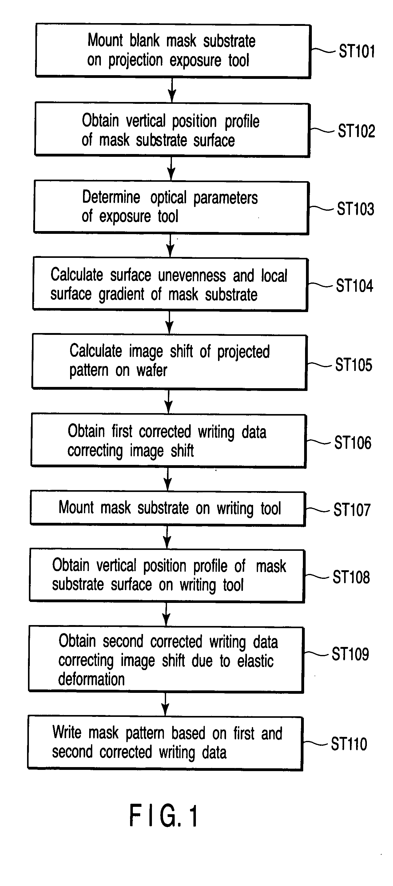
[0034]FIG. 1 is a flowchart showing a writing method according to a first embodiment of the present invention, and shows an outline of the present invention.

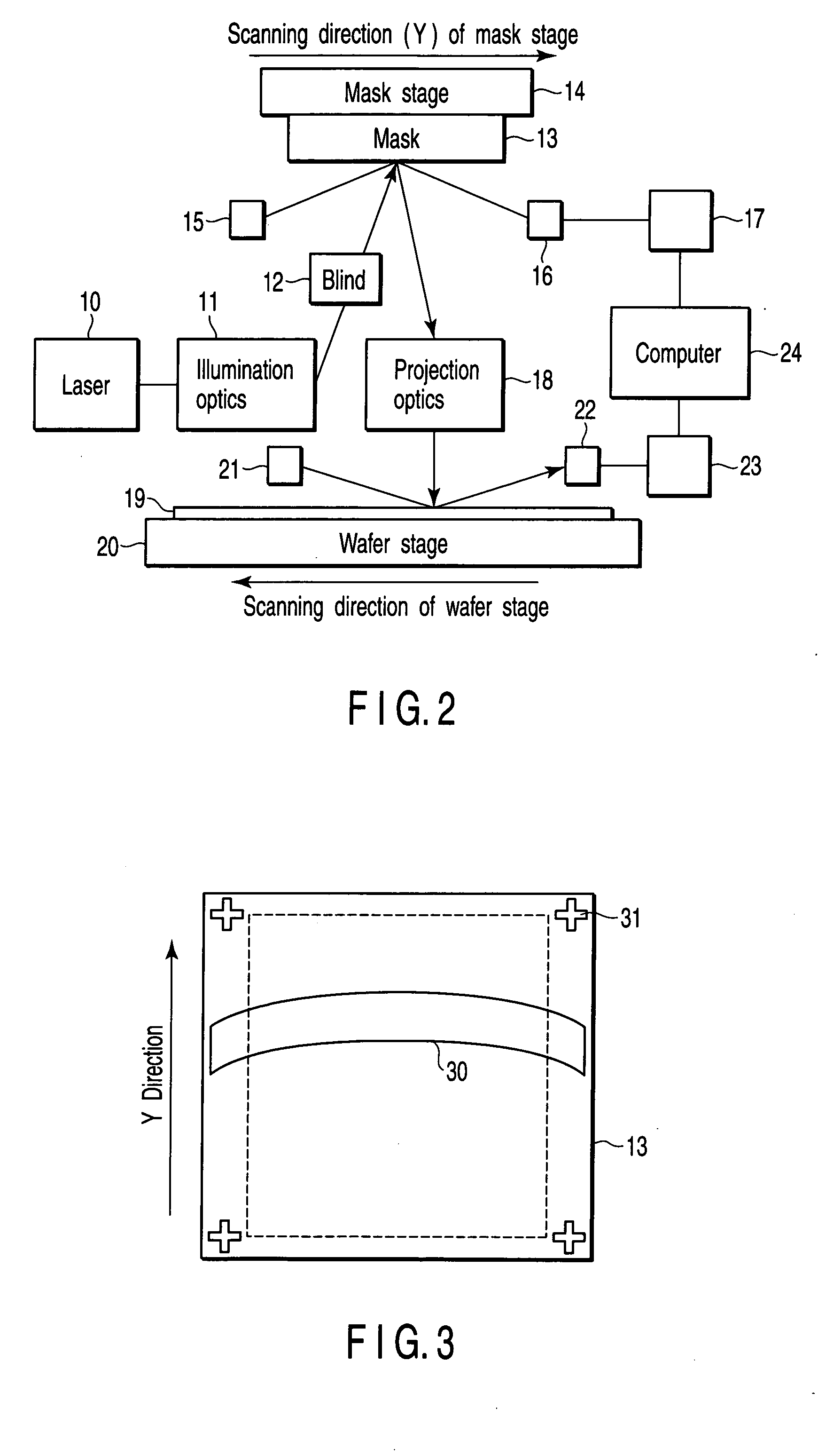
[0035] First, a blank mask substrate is mounted on a non-telecentric optical exposure tool for actual use (step ST101). A constitution of the non-telecentric optical exposure tool for actual use is illustrated in FIG. 2. In more detail, light of an EUV region is selected and emitted from a wavelength band of the light generated by a laser light source 10, and illuminative light is formed through an illumination optics 11 and a blind 12. An irradiation range 30 of the illuminative light has a substantially annular shape as shown in a schematic diagram of FIG. 3, and the light strikes on a mask substrate 13 at an angle of incidence of 6°. Reference numeral 31 denotes a fiducial mark. Next, the light which has illuminated the mask substrate 13 is reflected by the surface of the mask substrate 13, passes through projection optics 1...

second embodiment

[0068]FIG. 11 is a flowchart showing a writing method according to a second embodiment of the present invention.

[0069] In the present embodiment, even in a case where a mask substrate is not mounted on an exposure tool, surface unevenness of a mask at a time when the mask is mounted on the mask stage is predicted based on data of a mask stage surface shape and the shape of each blank mask which are measured (or inspected) beforehand, and a subsequent writing process is performed. In this case, since the substrate is not measured using the actual exposure tool, the exposure tool is not occupied for obtaining the mask surface shape, and there is no fear that productivity in an exposure step is degraded.

[0070] First, outline data of a mask stage chuck of the exposure tool is obtained (step ST201). As the chuck of the mask stage in step ST201, a flat or pin type electrostatic chuck, three-point supported electrostatic chuck, or four-point supported electrostatic chuck may be applied. ...


PUM

PropertyMeasurementUnit
angle of incidenceaaaaaaaaaa
sizeaaaaaaaaaa
flatnessaaaaaaaaaa

Abstract

A method of generating writing pattern data of a reflective mask for use in a non-telecentric exposure tool comprises obtaining a vertical position profile by measuring vertical positions of a plurality of X, Y coordinates arbitrarily set on the surface of a blank mask substrate when mounted on a mask stage, or by measuring and calculating a flatness profile, calculating unevenness of the blank mask substrate surface from the vertical position profile, calculating a shift amount of an image position, generated in a wafer mounted on a wafer stage of the exposure tool, in accordance with the unevenness of the blank mask substrate and parameters of a non-telecentric optics of the exposure tool, and obtaining corrected writing pattern data by correcting design pattern data of the reflective mask based on the shift amount of the image position and a reduction ratio of a projection optics of the exposure tool.

Description

CROSS-REFERENCE TO RELATED APPLICATIONS [0001] This application is based upon and claims the benefit of priority from prior Japanese Patent Application No. 2004-087820, filed Mar. 24, 2004, the entire contents of which are incorporated herein by reference. BACKGROUND OF THE INVENTION [0002] 1. Field of the Invention [0003] The present invention relates to a writing technique of a mask using an electron beam or laser beam, particularly to a method of generating writing pattern data of a mask for use in an extreme ultraviolet (EUV) lithography technique utilizing soft X-rays, and a method of writing a mask. [0004] 2. Description of the Related Art [0005] In recent years, as the next-generation lithography technique, an EUV lithography technique involving a reduced reflective-type projection exposure technique using 5- to 15-nm soft X-rays has been developed on a worldwide scale. In this lithography, since there is no substance (material) suitable for a refractive optical element in an...

Claims


Application Information

Patent Timeline
Patent Type & Authority Applications(United States)
IPC IPC(8): G03C11/00G03F1/00G03F1/24G03F1/36G03F1/68G03F1/70G03F7/20G03F9/00G06F17/50H01L21/027
CPCB82Y10/00B82Y40/00G03F7/70783G03F1/24G03F7/70433G03F1/144G03F1/70
Inventor MITSUI, SOICHIRO
Owner KIOXIA CORP
Why Eureka
Try Eureka