Control method for an exhaust gas purification system and an exhaust gas purification system

a technology of exhaust gas purification system and control method, which is applied in the direction of electrical control, engine starters, separation processes, etc., can solve the problems of filter clogging, exhaust pressure rise, and filter clogging progress, and achieve the effect of efficiently burning pm

Inactive Publication Date: 2005-10-06
ISUZU MOTORS LTD
View PDF8 Cites 17 Cited by
  • Summary
  • Abstract
  • Description
  • Claims
  • Application Information

AI Technical Summary

Benefits of technology

[0023] According to the control method of exhaust gas purifying system and the exhaust gas purifying device of the present invention, it is possible to keep the exhaust gas at a high temperature and to retain the temperature of the continuous regeneration-type DPF device during a stop condition of the vehicle, by closing an exhaust throttle valve of an exhaust-brake or an exhaust throttle executing an exhaust gas temperature raising control of a cylinder fuel injection such as a multi injection control, in the case where the vehicle stop

Problems solved by technology

However, these continuous regeneration-type DPF devices also cause the problem of exhaust pressure rise by the clogging of this filter.
However, in case of low exhaust gas temperature and in an operating condition of an internal combustion engine where the emission of NO is low, for example, in case where the low exhaust gas temperature state such as idling of internal combustion engine, low load/low speed operation continues, the oxidation reaction is not stimulated as the exhaust gas temperature is low, the catalyst temperature lowers and the catalyst is not activated and, moreo

Method used


Image

  • Control method for an exhaust gas purification system and an exhaust gas purification system
  • Control method for an exhaust gas purification system and an exhaust gas purification system
  • Control method for an exhaust gas purification system and an exhaust gas purification system

Examples


Embodiment Construction

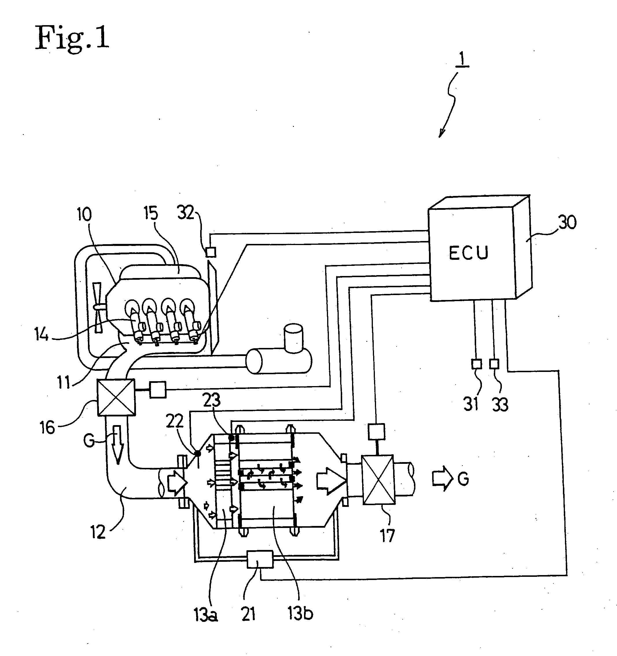
[0029] Hereinafter, the preferred embodiments of the control method for an exhaust gas purification system and the exhaust gas purification system according to the present invention will be described with reference to the accompanying drawings. The following explanation will use the example of an exhaust gas purification system provided with a continuous regeneration-type diesel particulate filter (DPF) device comprising a combination of an oxidation catalyst and a filter with catalyst.

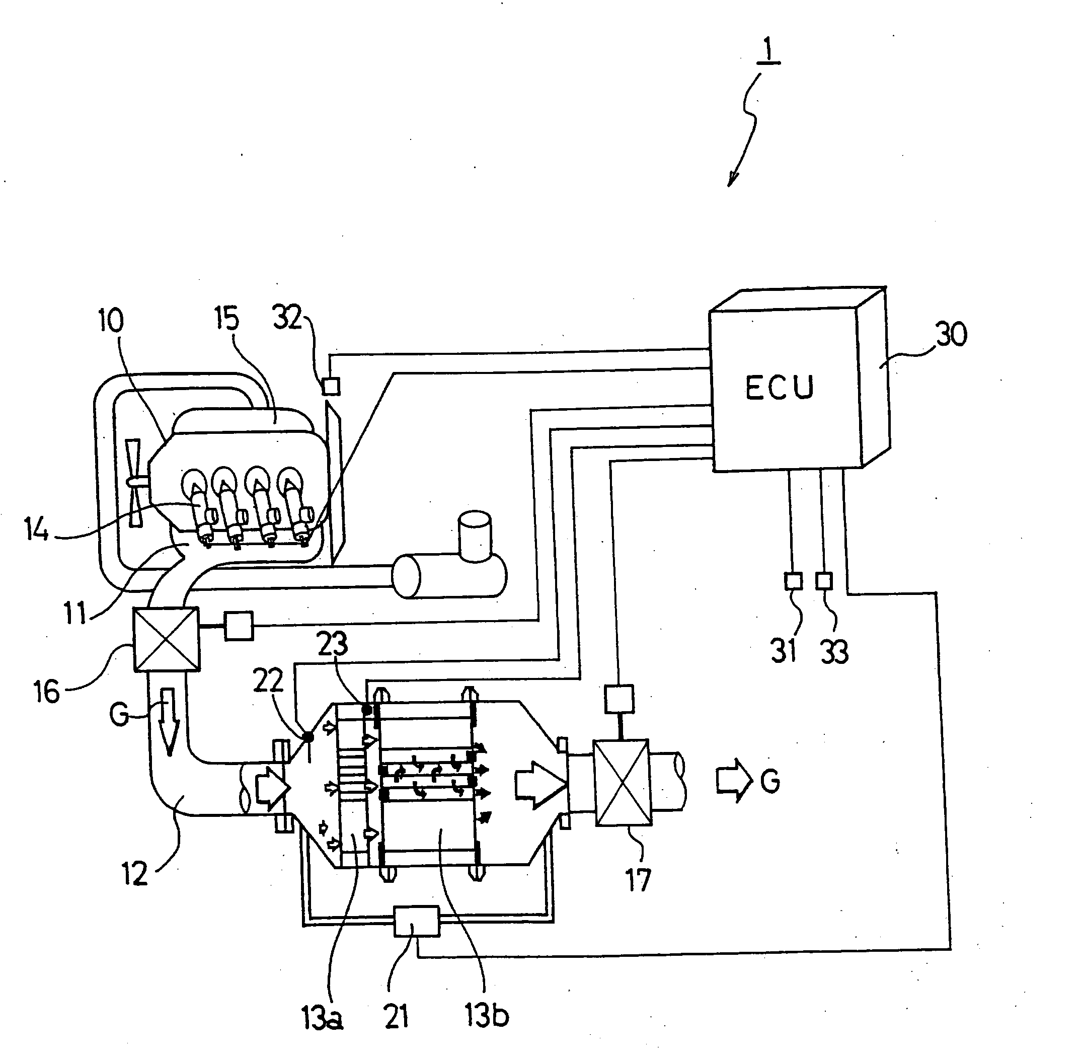
[0030]FIG. 1 shows the configuration of an exhaust gas purification system 1 for an internal combustion engine according to an embodiment of the present invention. This exhaust gas purification system 1 is configured to provide a continuous regeneration-type DPF device 13 on an exhaust passage 12 connected to an exhaust manifold 11 of a diesel engine 10. This continuous regeneration-type DPF device 13 is configured with an oxidation catalyst (DOC) 13a on the upstream side thereof and a filter with ca...


PUM

PropertyMeasurementUnit
Electric chargeaaaaaaaaaa
Temperatureaaaaaaaaaa

Abstract

An exhaust gas control system (1) comprised with a continuous regeneration-type DPF (13), an exhaust throttle valve (16) and a DPF control means (30C), wherein the regeneration control is suspended, the multi injection control is performed, and the exhaust throttle valve is closed, when detecting a stop condition of the vehicle during the regeneration control of the continuous regeneration-type diesel particulate filter device (13) by the regeneration means.
Thereby, concerning the regeneration of the continuous regeneration-type DPF device (13), the DPF can be regenerated securely by burning PM efficiently even in a traveling pattern of frequent waiting for the traffic lights to change in urban areas.

Description

BACKGROUND OF THE INVENTION [0001] The present invention relates to an exhaust gas purification system that purifies particulate matters (hereinafter “PM”) from the exhaust gas discharged by diesel and other internal combustion engines using a continuous regeneration-type diesel particulate filter (hereinafter “DPF”). [0002] In the same way as for NOx, CO, and also HC etc., restrictions on the volume of PM discharged from internal combustion engines such as diesel engines grow severe every year. Techniques for collecting this PM in a filter known as a DPF and for reducing the quantity thereof by discharging externally have been developed. [0003] DPFs for collecting this PM include a monolithic honeycomb form wall flow type filter made of ceramic, a fiber form type filter made of fiber shape ceramic or metal, and so on. An exhaust gas control system using one of these PDFs are installed on the way of the exhaust passage of an internal combustion engine, similarly to the other exhaust...

Claims


Application Information

Patent Timeline
IPC IPC(8): F02D9/04B01D46/42F01N3/02F01N3/023F01N3/025F01N3/029F01N3/035F01N3/18F01N3/20F01N13/02F02D41/02F02D41/04F02D41/38F02D41/40F02D43/00F02D45/00F02N11/08
CPCF01N3/035F01N2390/00F01N2430/085F02D9/04F02D41/021F01N13/0097F02D41/029F02D41/08F02D41/1446F02D41/402F02D2200/501F02D41/0245
Inventor SATO, HITOSHIHIRAKI, NOBUYUKIIMAI, TAKEHITO
Owner ISUZU MOTORS LTD
Why Eureka
Try Eureka