High performance embedded RF filters

a filter and high-performance technology, applied in the direction of layered products, waveguide devices, chemistry apparatus and processes, etc., can solve the problems of occupying valuable board space, and expensive edge-coupled stripline resonators

Inactive Publication Date: 2005-10-06
LAMINA LIGHTING
View PDF12 Cites 9 Cited by
  • Summary
  • Abstract
  • Description
  • Claims
  • Application Information

AI Technical Summary

Problems solved by technology

Presently such RF filters are made as discrete, surface mounted components, e.g., edge-coupled stripline resonators, which are expensive.
Further, they take up valuable board space that could be given over to incorporation of additional functions on the board, or to reduce the overall size and weight of the ceramic circuit board.
Embedded RF filters including strip conductors in a ceramic circuit board stack have been tried, but the performance results are no more than marginal for insertion loss and selectivity.

Method used


Image

  • High performance embedded RF filters
  • High performance embedded RF filters

Examples


Embodiment Construction

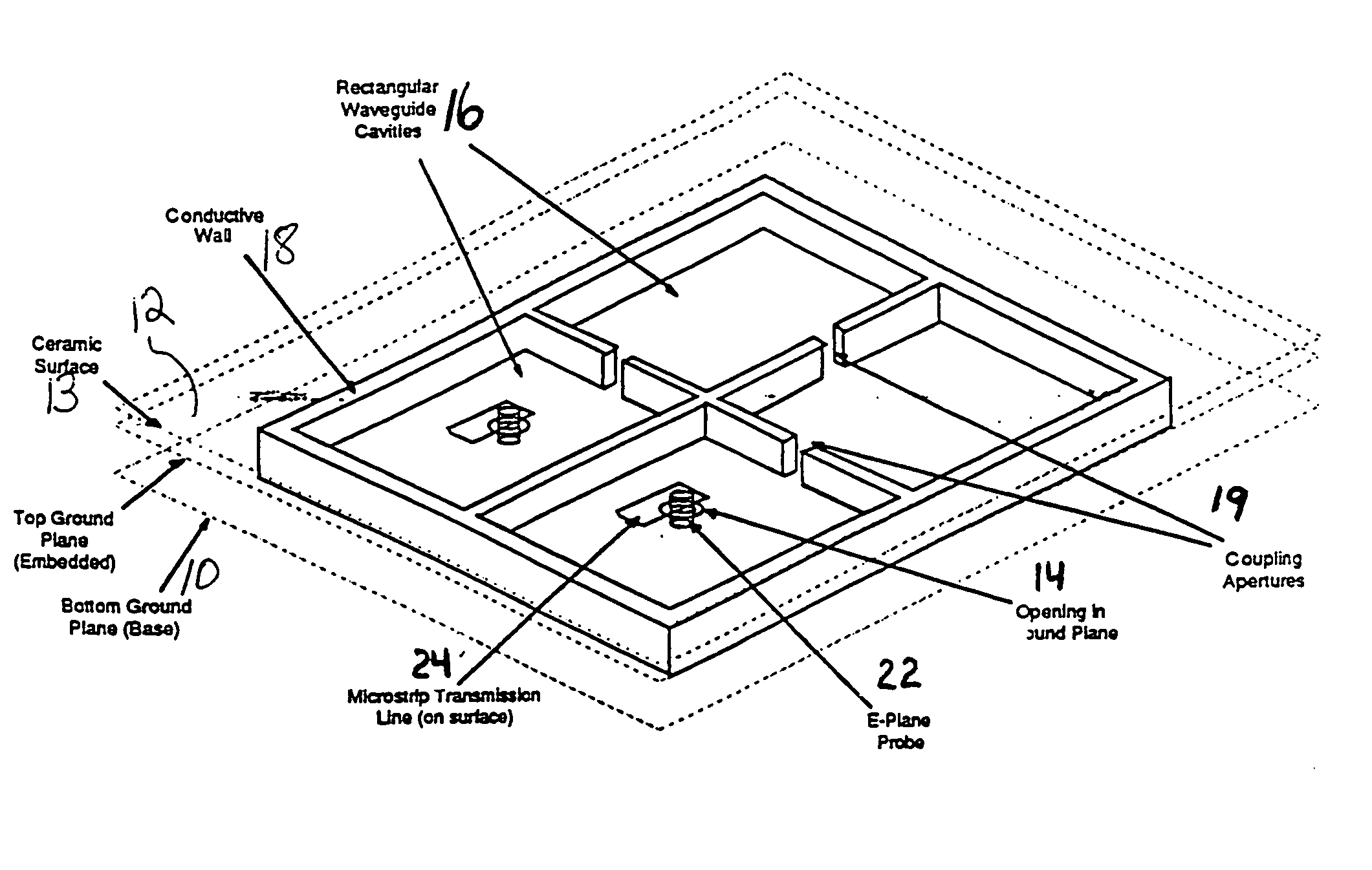
[0016] The embedded RF filters of the invention comprise a plurality of dielectric filled waveguide resonators having dimensions defined by conductors on the top, bottom and sidewalls. These volumes can have various sizes and shapes, depending on the operating frequency and resonant mode desired. The cavities are coupled together by means of apertures formed in the interior walls. The position and size of these apertures can also be adjusted depending on the degree of coupling desired.

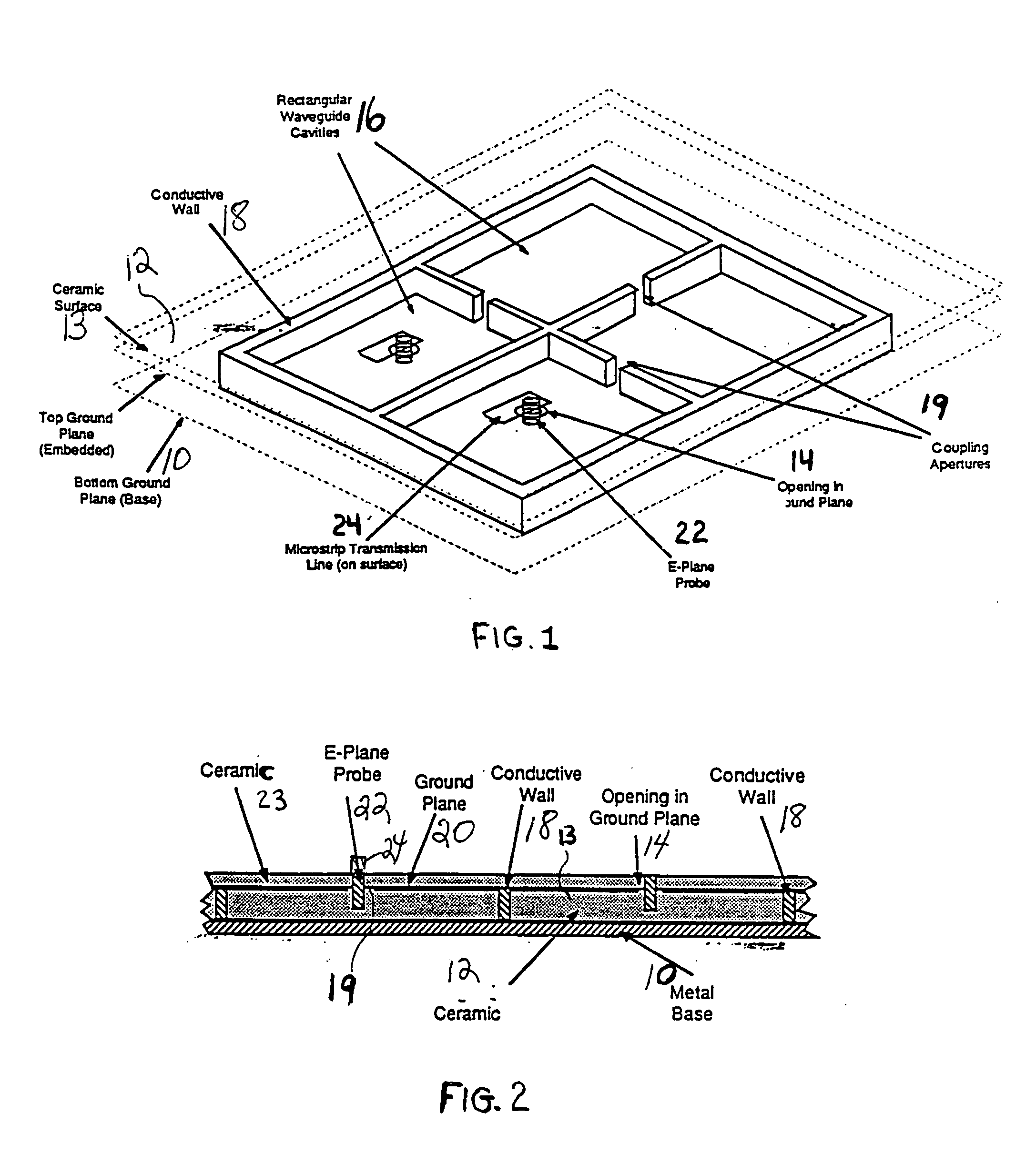
[0017]FIG. 1 illustrates an embedded RF filter that can be made according to the present invention. FIG. 2 is a cross sectional view thereof.

[0018] Referring to FIGS. 1 and 2, metal support or ground plane 10 has a first green tape stack 12 mounted thereon having a surface 13. This green tape stack 12 is punched to provide openings for conductive walls 18 and coupling apertures 19 forming cavities 16, and openings 14 for insertion therein of E-plane probes 22. The cavity walls 18 and coupling apertur...


PUM

PropertyMeasurementUnit
temperaturesaaaaaaaaaa
weightaaaaaaaaaa
weightaaaaaaaaaa

Abstract

Embedded, coupled, shaped waveguide resonators having conductive walls sandwiched between two fired green tape stacks, said conductive walls having apertures therein whose size and location determine the degree of coupling. These waveguides are made by forming openings in a first green tape stack, defining walls and apertures therein, mounting a second green tape stack having a conductive layer thereon thereover and firing the assembly. E-plane probes are inserted in openings in the second green tape stack and connected to microstrip transmission lines on an external surface pf this green tape stack.

Description

RELATED APPLICATIONS [0001] This application claims the benefit of U.S. Provisional application Ser. No. 60 / 106,313, filed Oct. 30, 1998. [0002] This invention relates to embedded RF filters. More particularly, this invention relates to multilayer ceramic printed circuit boards including embedded RF filters having high performance.GOVERNMENT SUPPORT [0003] This invention was at least partially supported by the Government Contract No. F33615-96-2-5105. The government may have certain rights in this invention.BACKGROUND OF THE INVENTION [0004] Low temperature firing multilayer ceramic circuit boards are known that are suitable for use with low melt temperature conductive metals, such as silver, gold and copper. They have a low thermal coefficient of expansion (TCE) and they may be formulated to be compatible with both silicon and gallium arsenide devices. [0005] These ceramic circuit boards are made from glasses that can be fired at low temperatures, e.g., temperatures of less than 10...

Claims


Application Information

Patent Timeline
Patent Type & Authority Applications(United States)
IPC IPC(8): H01P1/208H01P7/06H01L23/12H01P11/00
CPCH01P1/2088Y10T156/1057Y10T156/1056H01P11/008
Inventor GELLER, BERNARD DOVFATHY, ALY EIDLIBERATDORE, MICHAEL JAMESSREERAM, ATTIGANAL NARAYANSWAMYTHALER, BARRY JAY
Owner LAMINA LIGHTING
Why Eureka
Try Eureka