Detector of differential threshold voltage

a detection circuit and threshold voltage technology, applied in the field of differential voltage level detection, can solve the problems of increasing the area of the integrated circuit, requiring increased power, and not responding significantly to identical changes in input pairs

Inactive Publication Date: 2005-10-06
ATMEL CORP
View PDF13 Cites 9 Cited by
  • Summary
  • Abstract
  • Description
  • Claims
  • Application Information

AI Technical Summary

Benefits of technology

[0014] Within the front-end voltage shifter, there is one voltage shifting circuit for each component of an input differential voltage pair. The voltage reference output is connected to each voltage shifting circuit generating an essentially equal calibrated current in each voltage shifting circuit. The voltage shifting circuit produces both the shifted version and the non-shifted version of the differential input voltage pair. The non-shifted version is produced in phase with the shifted version for comparison purposes.

Problems solved by technology

Additionally, most differential detection circuits do not respond significantly to identical changes in the input pairs that may be induced by noise, process, or temperature influences.
This maximizes power consumption.
However, these references all suffer disadvantages in at least one of the following areas: allow for the application of a reference current to generate a shift in voltage of a differential signaling structure enabling setting precisely calibrated levels of detection; create paired high-level and low-level signal sets, mutually calibrated from a single source, suitable for direct app

Method used


Image

  • Detector of differential threshold voltage
  • Detector of differential threshold voltage
  • Detector of differential threshold voltage

Examples


Embodiment Construction

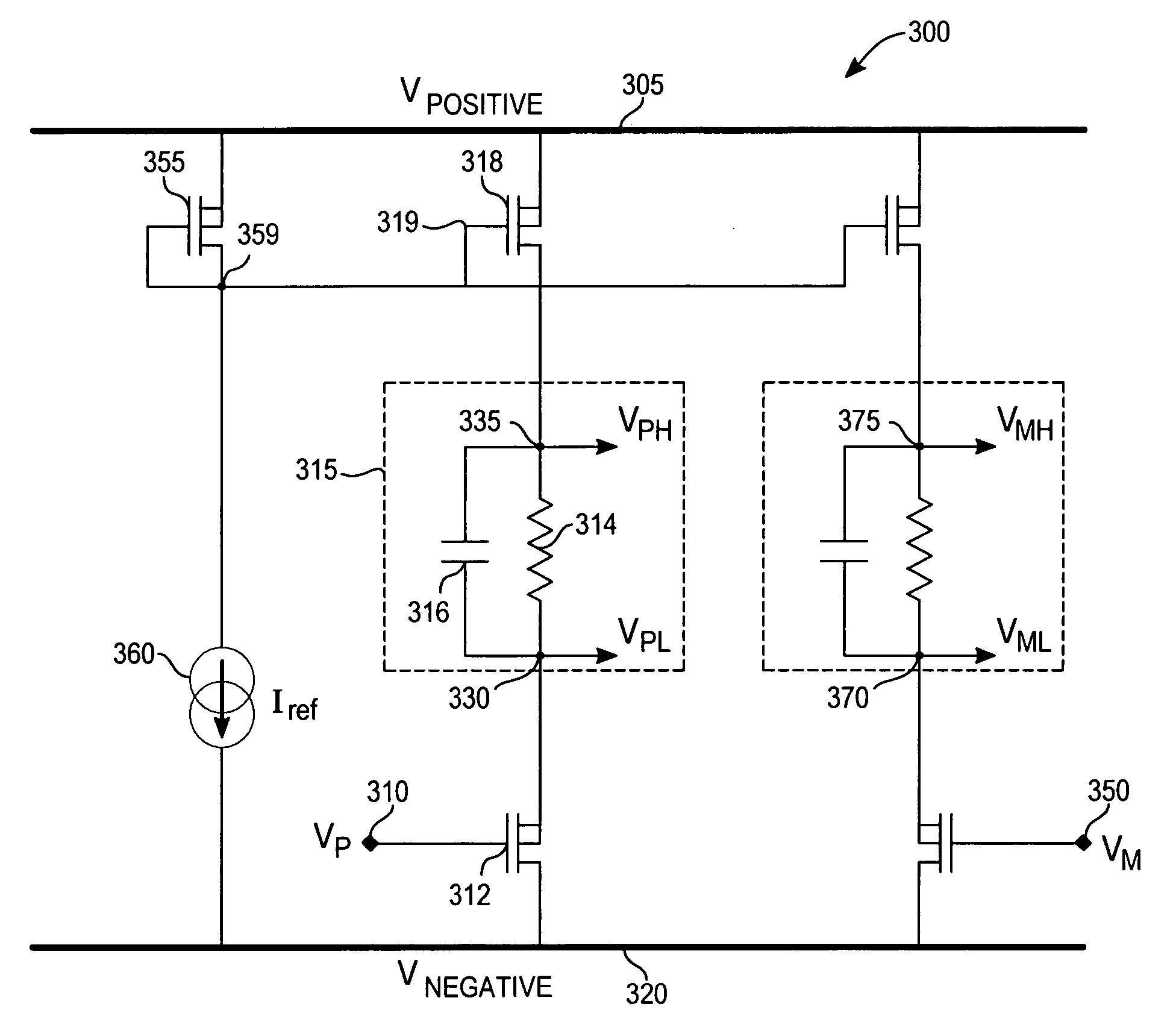
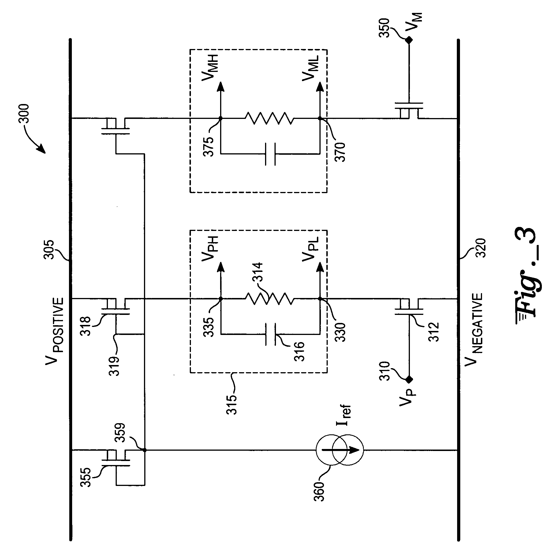
[0025] With respect to FIG. 3, an exemplary embodiment of a front-end level shifter 300 includes a series coupling of a voltage generating PMOS transistor 355 and a current reference 360 between a positive power bus 305 and a negative power bus 320. The voltage generating PMOS transistor 355 and a current reference 360 form a current mirror producing a reference voltage at a voltage reference terminal 359.

[0026] A positive signal component of a complementary differential voltage pair is connected at a positive differential input 310 (VP) of a first differential input PMOS transistor 312. The first differential input PMOS transistor is coupled with a source terminal to a positive differential—low terminal 330 (VPL) and a drain terminal to the negative power bus 320. A first voltage shifting circuit 315 is coupled between the positive differential—low terminal 330 and a positive differential—high terminal 335 (VPH). The first voltage shifting circuit 315 contains a parallel connectio...


PUM


Abstract

A differential threshold voltage level detection circuit receives a differential voltage pair as an input, applying each component of the differential pair to an individual voltage shifting circuit. Each voltage shifting circuit is configured with a regulated current producing a shifted and a non-shifted version in-phase. For a shifted set of output differential voltages, the shift magnitude is proportional to the current entering a shifting circuit and is configured to be less than a peak-to-peak magnitude of the differential voltage to be detected. A current mirror within the detector contains a current reference configured to produce a current to be passed through a voltage generator. The current magnitude is sufficient to generate a regulated voltage output to the two current regulating devices that supply the voltage shifting circuits. An overlap detector receiving both differential voltage pairs produces a signal indicating an input is at a detection threshold.

Description

TECHNICAL FIELD [0001] The present invention relates to the field of differential voltage level detection. More specifically, the present invention relates to the detection of high-speed differential signals based on sensing their overlap with a reference threshold level. BACKGROUND ART [0002] Differential signals are used for inexpensive, high speed, low power, and noise immune communication. Differential signal pairs have complementary voltage components transitioning in potential in opposite directions. This complementary transitioning allows communication with signals at lower peak-to-peak voltages since receivers can have input thresholds more optimally controlled than single ended detectors. The lower voltage swings mean lower power requirements. [0003] Differential threshold detection typically involves a detector circuit taking, as input, a differential input signal component and producing a voltage or current quantity in response to changes in that input signal. The detecto...

Claims


Application Information

Patent Timeline
IPC IPC(8): G06F13/40H03B1/00H03K5/003H03K5/08H03K19/003
CPCH03K5/003H03K19/00323H03K5/08
Inventor AJRAM, SAMISTRAZZIERI, FRANCKGARCIA, FLORENT
Owner ATMEL CORP
Why Eureka
Try Eureka