
All-optical linear feedback shift register

a technology of shift register and optical feedback, applied in the field of linear feedback circuit, can solve the problems of large form factor, unauthorized user, and relatively expensive components of current prbs generating systems implementing lfsrs, and achieve the effect of high data ra

Active Publication Date: 2005-10-06
LGS INNOVATIONS
View PDF3 Cites 12 Cited by
  • Summary
  • Abstract
  • Description
  • Claims
  • Application Information

AI Technical Summary

Benefits of technology

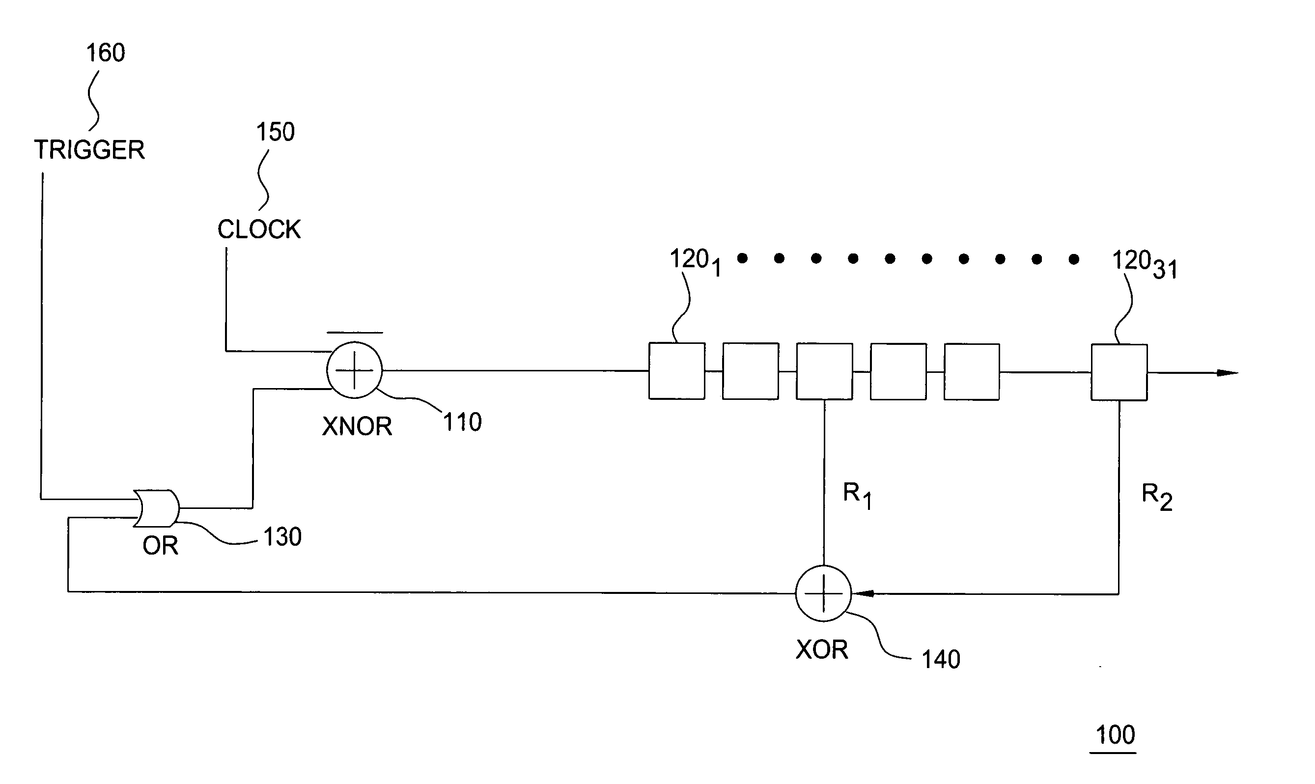
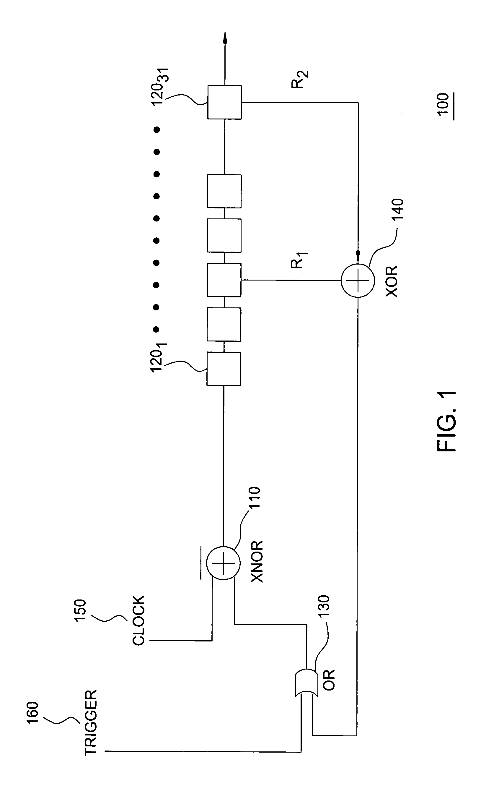
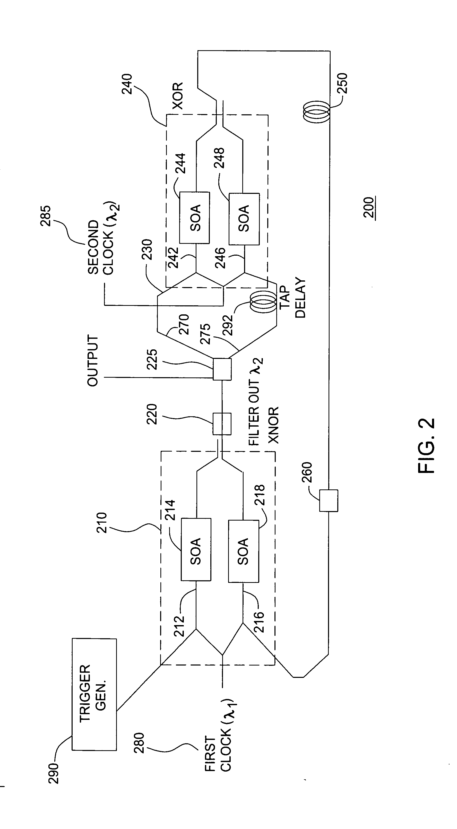
"The present invention provides an all-optical linear feedback circuit that can generate 2N-1 bit maximal length PRBS sequences at high data rates using an optical semiconductor amplifier. The circuit includes a delay circuit with at least two optical paths, each containing a nonlinear element for imparting an intensity-dependent phase modulation on a combined signal propagating therein. The output of the circuit is split and propagates along each of the optical paths, resulting in a delay in the optical path with the delay element. The circuit also includes a first optical logic circuit with at least two inputs for receiving a clocking signal, a trigger signal, and a feedback signal, and an output coupler for providing a Boolean logic output of a combination of the signals propagating in the at least two optical paths. The second optical logic circuit has at least two inputs for receiving a delayed signal from the first optical path and a second optical path, each containing a nonlinear element for imparting an intensity-dependent phase modulation on a combined signal propagating therein. The output of the second logic circuit functions as the feedback signal received by the first logic circuit. The technical effect of this invention is the ability to generate high-speed PRBS sequences with a high data rate using an all-optical linear feedback circuit."

Problems solved by technology

An unauthorized user, who does not have the knowledge of either the encryption method (e.g., the encryption algorithm) or the key formed based on the encryption method, cannot easily decode the information.
Therefore, even if the unauthorized user obtains the scrambled data, the knowledge of both of the encryption method and the particular key is needed to decrypt the confidential information embedded therein.
Furthermore, current PRBS generating systems implementing LFSRs have large form factors and include relatively expensive components.

Method used


Image

  • All-optical linear feedback shift register
  • All-optical linear feedback shift register
  • All-optical linear feedback shift register

Examples


Embodiment Construction

[0001] This invention was made with Government support pursuant to Contract No. MDA904-03-C-0413 awarded by the National Security Agency. The Government has certain rights in the invention.

FIELD OF THE INVENTION

[0002] This invention relates to linear feedback circuits and, more specifically, to an all-optical linear feedback circuit.

BACKGROUND OF THE INVENTION

[0003] The use of linear feedback shift registers (LFSRs) is well known in integrated circuit technology. LFSRs may be used in a number of applications. For example, a LFSR may be used to implement a clock divider circuit. A clock divider circuit is used to divide a master clock signal to obtain a different frequency clock signal. A LFSR (n bit width) may also be used as both a test data generation circuit and a test result generation circuit. A LFSR serving as a test data generation circuit typically includes a simple register circuit including serial-connected n D-type flip-flops and a feedback circuit for generating an ex...


PUM

PropertyMeasurementUnit
optical pathsaaaaaaaaaa
path lengthaaaaaaaaaa
opticalaaaaaaaaaa

Abstract

An all-optical linear feedback circuit for use, for example, as a maximal length pseudo random bit sequence generator includes an all-optical logic circuit that is capable of generating 2N−1 bit maximal length pseudo random bit sequences on an optical channel at high data rates e.g. 80 Gbit / s. In the pseudo random bit sequence generator of the present invention, intensity-dependent phase modulation of at least one included semiconductor optical amplifier (SOA) is implemented. The maximum data rate is limited by the fast gain recovery time of the carriers in the SOA. An optical logic gate of the pseudo random bit sequence generator of the present invention may be constructed using various nonlinear elements that provide ultra-fast intensity-dependent phase modulation.

Description

STATEMENT OF GOVERNMENTAL INTEREST [0001] This invention was made with Government support pursuant to Contract No. MDA904-03-C-0413 awarded by the National Security Agency. The Government has certain rights in the invention.FIELD OF THE INVENTION [0002] This invention relates to linear feedback circuits and, more specifically, to an all-optical linear feedback circuit. BACKGROUND OF THE INVENTION [0003] The use of linear feedback shift registers (LFSRs) is well known in integrated circuit technology. LFSRs may be used in a number of applications. For example, a LFSR may be used to implement a clock divider circuit. A clock divider circuit is used to divide a master clock signal to obtain a different frequency clock signal. A LFSR (n bit width) may also be used as both a test data generation circuit and a test result generation circuit. A LFSR serving as a test data generation circuit typically includes a simple register circuit including serial-connected n D-type flip-flops and a fe...

Claims


Application Information

Patent Timeline
Patent Type & Authority Applications(United States)
IPC IPC(8): G02F3/00G06E1/02H03K3/84H03M1/22
CPCG02F3/00H03K3/84G06E1/02G02F2203/70
Inventor BHARDWAJ, ASHISHJAQUES, JAMES J.
Owner LGS INNOVATIONS
Learn More