
Debulking catheters and methods

a technology of debulking catheter and body lumen, which is applied in the field of atherectomy catheters, can solve the problems of reclosure or blockage of the body lumen, myocardial infarction, and many currently available side-cutting atherectomy catheters have difficulty in capturing occluding material in the cutting aperture, so as to facilitate the removal of material, improve material and shape, and enhance the removal of occlusive material

Inactive Publication Date: 2005-10-06
TYCO HEALTHCARE GRP LP
View PDF3 Cites 101 Cited by
  • Summary
  • Abstract
  • Description
  • Claims
  • Application Information

AI Technical Summary

Benefits of technology

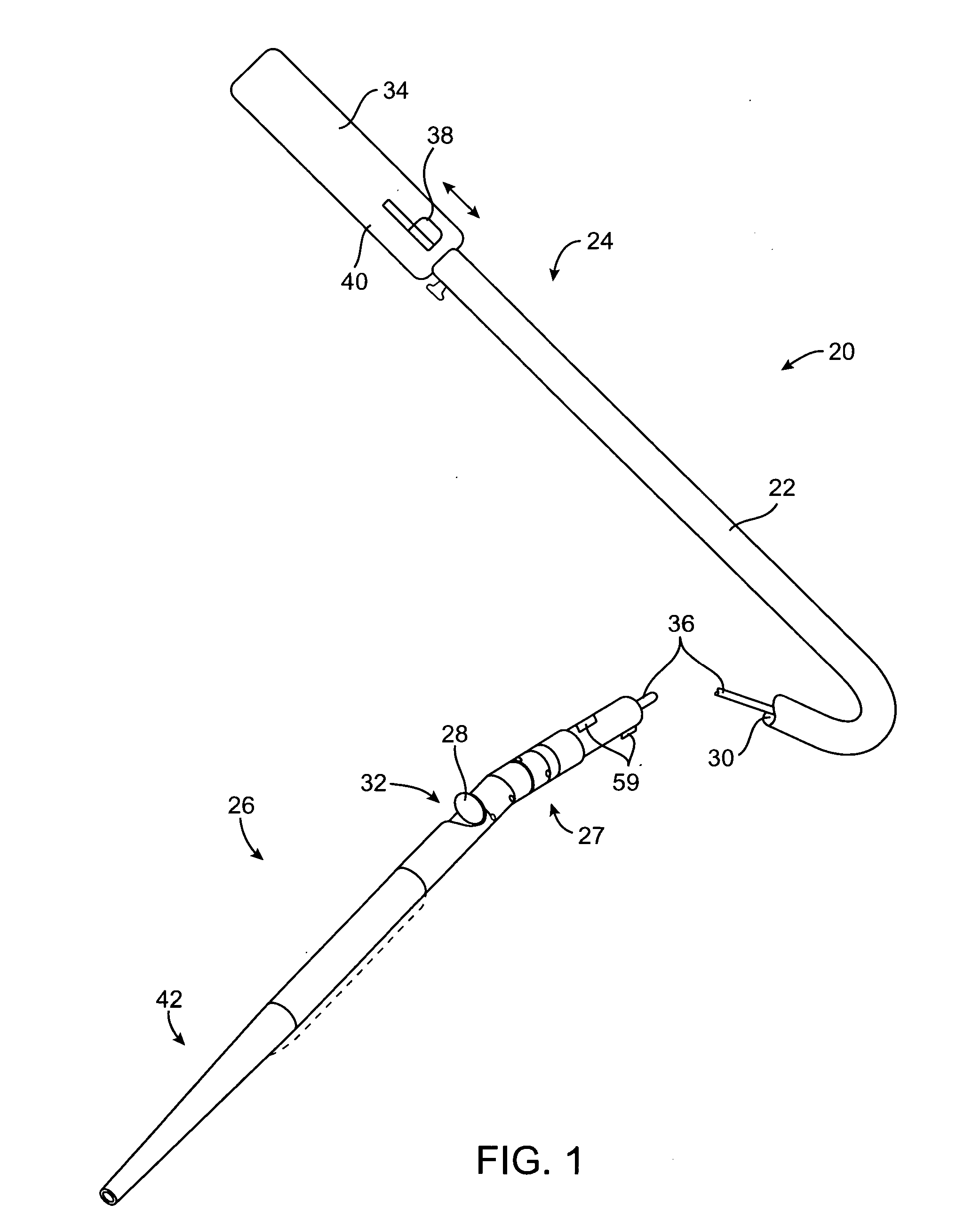
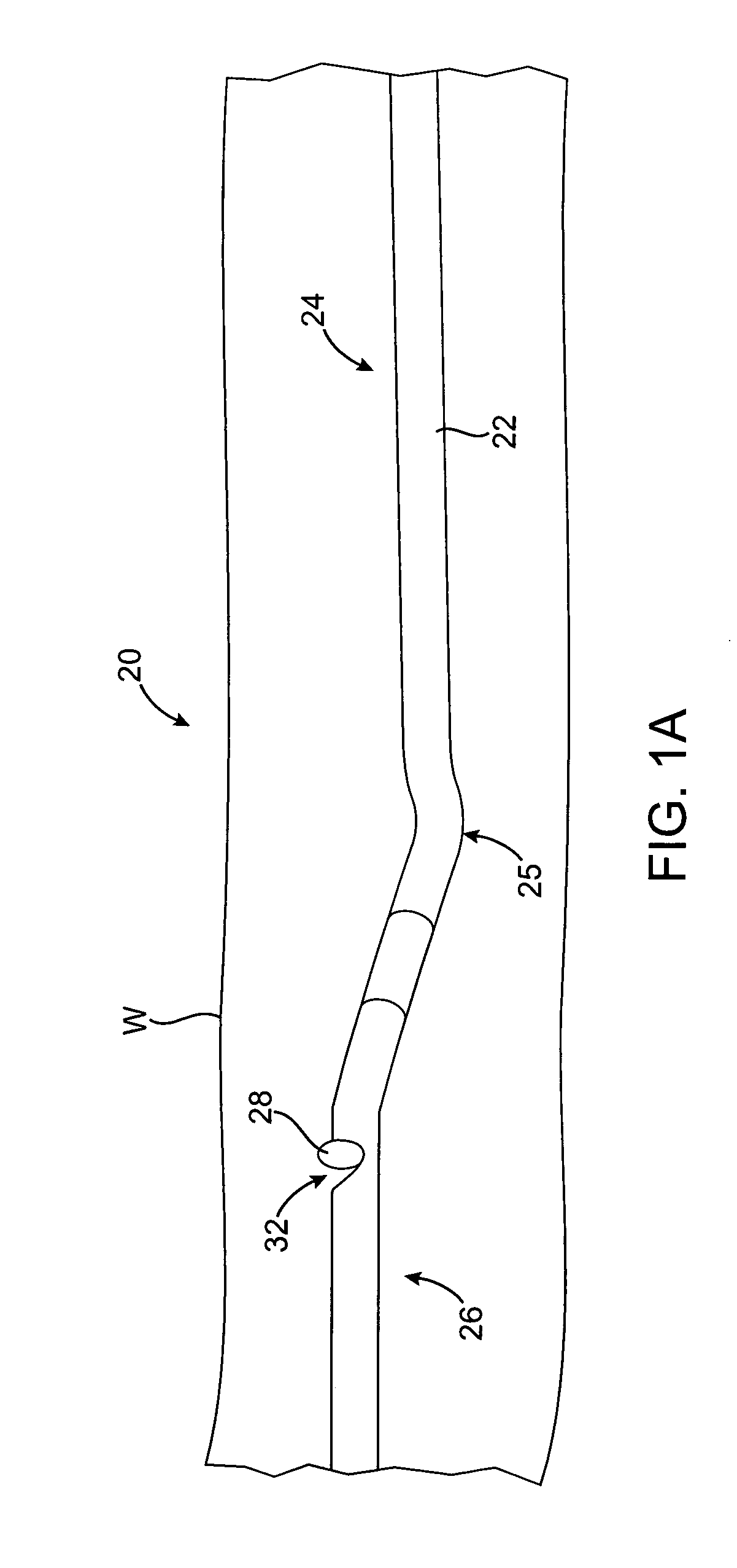
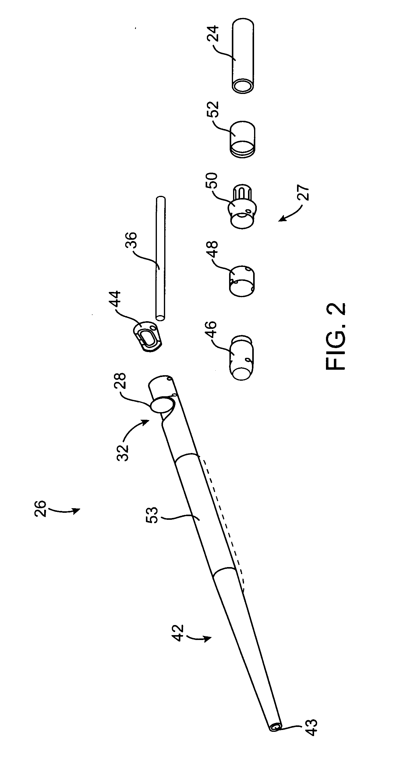
[0011] Catheters of the present invention are configured to enhance the removal of occlusive material from a body lumen by providing catheters with one or more improved features. For example, some embodiments include a deflected or deflectable portion of the catheter, such as a distal portion that is deflectable relative to the proximal portion or a deflected or deflectable section near the distal end of the proximal portion. Such deflection may help to urge a portion of the catheter into contact with material adhered to the sidewall of a body lumen to facilitate removal of the material. Deflection may also expose the tissue debulking assembly through the window on the catheter body. In various embodiments, other advantageous features of the catheters of the present invention include, but are not limited to, telescoping guidewire lumens, a shuttle mechanism for locking the tissue debulking assembly in a given position, debulking assemblies having improved materials and shapes, imaging devices, improved material storage tips and the like.
[0012] In one aspect of the present invention, a debulking catheter for removing material from a body lumen includes a catheter body and a tissue debulking assembly. The catheter body generally includes a proximal portion and a distal portion, with the distal portion having a window. The tissue debulking assembly is disposed at least partially within the distal portion of the catheter body and is radially movable to expose at least a portion of the assembly through the window to contact the material in the body lumen. The tissue debulking assembly itself may take any of a number of suitable forms, but in one embodiment it comprises a rotatable cutter. Optionally, such a cutter may include a beveled edge for contacting the material in the body lumen while preventing injury to the body lumen. In some embodiments, the cutter includes a tungsten carbide cutting edge for improved durability and cutting ability. In still other embodiments, the tissue debulking assembly may comprise a radio frequency electrode, a laser, an ultrasound emitter and / or the like.

Problems solved by technology

Atheromatous and other vascular deposits restrict blood flow and can cause ischemia which, in acute cases, can result in myocardial infarction.
One factor impeding the success of stent technology in endoluminal treatments is the frequent occurrence of in-stent restenosis, characterized by proliferation and migration of smooth muscle cells within and / or adjacent to the implanted stent, causing reclosure or blockage of the body lumen.
For example, many currently available side-cutting atherectomy catheters have difficulty in capturing occluding material in the cutting aperture.
Since most cutter housings are rigid, such lengthening makes it more difficult to introduce the distal end of the catheter through tortuous regions of the vasculature.
Such balloons, however, unduly increase the size of the distal portion of the catheter.
Even with the balloon, the amount of material that can be removed by conventional atherectomy catheters is limited by the size of the cutting window.
Other disadvantages of some catheters include cutting elements with less than ideal hardness, inadequate storage space within the catheter for containing removed material, sub-optimal guide wire lumens, and / or the like.
In addition, the available atherectomy catheters generally provide material insufficient in quantity and / or quality for testing by many histological, array, proteomic or other biochemical or molecular methods.
This amount of material is not typically enough to carry out more than one test, or is insufficient to successfully carry out a number of diagnostic tests available to the physician or researcher.

Method used


Image

  • Debulking catheters and methods
  • Debulking catheters and methods
  • Debulking catheters and methods

Examples


Embodiment Construction

[0065] The catheters and methods of the present invention are designed to debulk atheroma and other occlusive material from diseased body lumens, and in particular coronary arteries, de novo lesions, and in-stent restenosis lesions. The catheters and methods, however, are also suitable for treating stenoses of body lumens and other hyperplastic and neoplastic conditions in other body lumens, such as the ureter, the biliary duct, respiratory passages, the pancreatic duct, the lymphatic duct, and the like. Neoplastic cell growth will often occur as a result of a tumor surrounding and intruding into a body lumen. Debulking of such material can thus be beneficial to maintain patency of the body lumen. The catheters and methods of the present invention also provide methods that provide lumenectomy samples or materials that are of higher quality and quantity that typically have been provided by prior devices. The material provided is typically a continuous strip of tissue removed from the...


PUM


Abstract

A debulking catheter comprising a tissue debulking assembly for removing a continuous strand of material from a body lumen. Catheters of the present invention generally include a catheter body having proximal and distal portions and a tissue debulking assembly disposed at least partially within the distal portion. The tissue debulking assembly is radially movable to expose at least a portion of the assembly through a window on the catheter body. The catheter is advanced transluminally through the body lumen to contact material in the body lumen and remove a plane of continuous material that has a length that is typically longer than a length of the window on the catheter. The continuous material may be directed into a collection chamber. Thereafter, the material may be removed from the collection chamber and preserved or tested.

Description

CROSS-REFERENCES TO RELATED APPLICATIONS [0001] The present application is a continuation-in-part of U.S. patent application Ser. No. 10 / 896,741, filed Jul. 21, 2004, which is a continuation-in-part of U.S. patent application Ser. No. 10 / 288,559, filed Nov. 4, 2002, which is a continuation-in-part of U.S. patent application Ser. No. 10 / 027,418, filed Dec. 19, 2001, which claims the benefit of Provisional Patent Application Ser. No. 60 / 257,704, filed Dec. 20, 2000, and Provisional Patent Application Ser. No. 60 / 272,273 filed Feb. 27, 2001, the complete disclosures of which are incorporated herein by reference. [0002] Application Ser. No. 10 / 896,741 also claims the benefit of Provisional Application No. 60 / 381,632, filed on May 19, 2002, the complete disclosure of which is incorporated herein by reference. The present application is also related to U.S. patent application Ser. No. 09 / 377,884, filed Aug. 19, 1999, and Ser. No. 09 / 377,894, filed Aug. 19, 1999, entitled the complete disc...

Claims


Application Information

Patent Timeline
Patent Type & Authority Applications(United States)
IPC IPC(8): A61B17/22A61B10/02A61B10/04A61B10/00
CPCA61B10/0096A61B10/02A61B10/0266A61B10/04A61B17/320725G16H10/60A61B17/320783A61B2017/00778A61B2017/320791A61B90/90A61B17/320758
Inventor SIMPSON, JOHN B.
Owner TYCO HEALTHCARE GRP LP
Learn More