Flexible good conductive layer and anisotropic conductive sheet comprising same

a conductive layer and anisotropic technology, applied in the direction of conductors, non-metal conductors, coupling device connections, etc., can solve the problems of difficult shortening the distance between such thin metal wires, anisotropic conductive films may not keep their function to a sufficient degree, and the electric conduction becomes insufficient in the direction of the plane, so as to improve the adhesion, improve the adhesion, and reduce the effect of thermal expansion differences

Inactive Publication Date: 2005-10-13
JST MFG CO LTD
View PDF20 Cites 14 Cited by
  • Summary
  • Abstract
  • Description
  • Claims
  • Application Information

AI Technical Summary

Benefits of technology

[0036] The anisotropic conductive sheet of the present invention, further, may be characterized in that the flexible good conductive layer comprises the adhesive layer and the conductive layer. Here, the adhesive layer may be the one for improving the adhesion to the conductive members while the flexible good conductive layer comes in contact with the conductive members. The conductive layer of the flexible good conductive layer has physical and chemical properties, which are greatly different from the physical and chemical prope

Problems solved by technology

When the rigidity of the substrate on which the conductive layer is deposited is not sufficient, however, the substrate is distorted due to bending, twisting, stretching or contraction when being handled, whereby the distortion is transmitted to the conductive layer which is, then, deformed to develop cracking resulting in a destruction.
It is therefore probable that the electric conduction becomes insufficient in the direction of the plane.
In the anisotropic conductive film with thin metal wires, however, it is

Method used


Image

  • Flexible good conductive layer and anisotropic conductive sheet comprising same
  • Flexible good conductive layer and anisotropic conductive sheet comprising same
  • Flexible good conductive layer and anisotropic conductive sheet comprising same

Examples


Embodiment Construction

[0063] The present invention will now be described in further detail by way of embodiments with reference to the drawings. However, the embodiments are simply to illustrate concrete materials and numerical values as preferred examples of the present invention, but are not to limit the present invention.

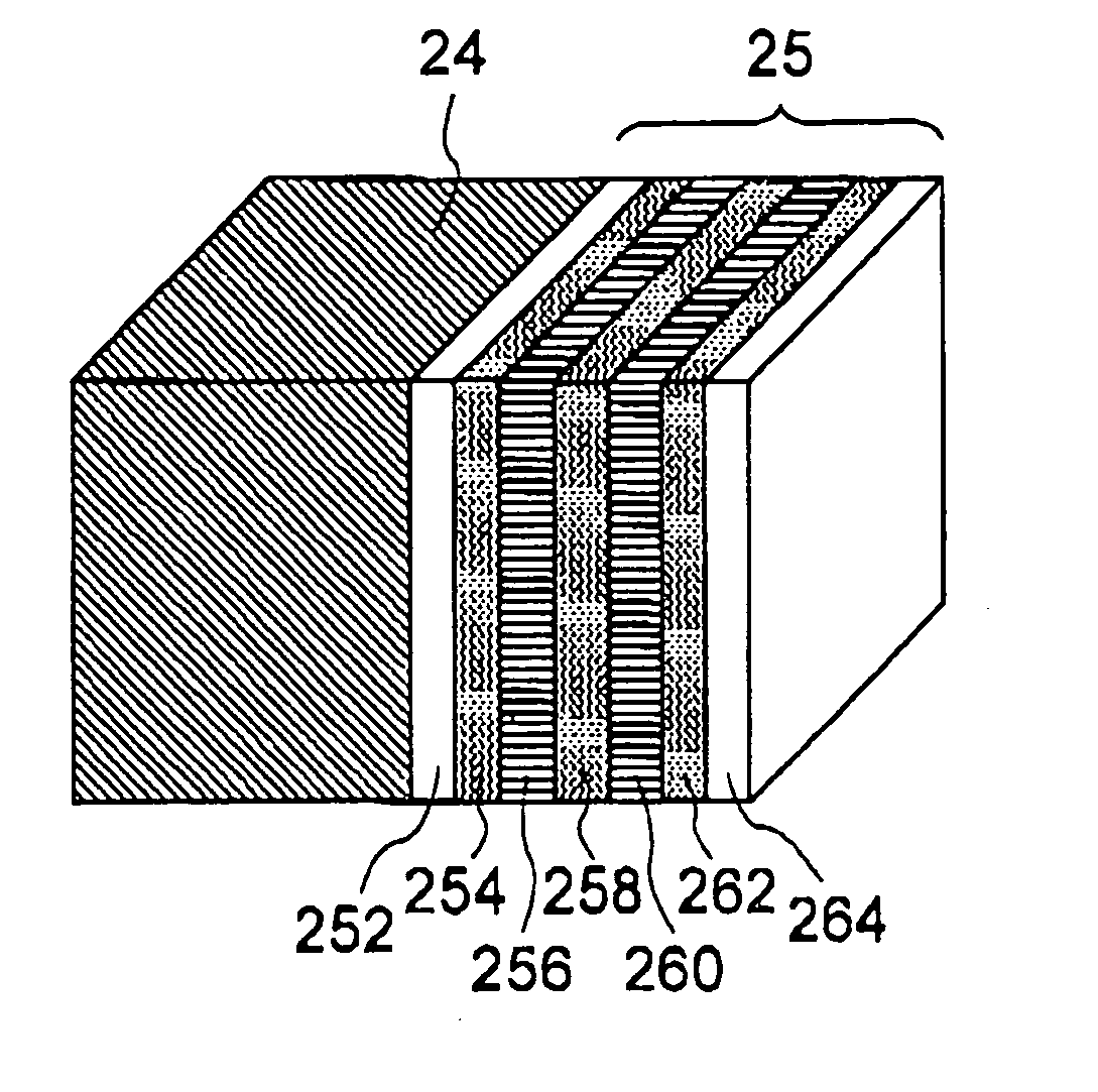
[0064]FIG. 1 schematically illustrates a flexible good conductive layer 25 according to an embodiment of the present invention in a form adhered to a base member 24. The base member 24 is made of a flexible material and, in this embodiment, is made of a conductive elastomer. The above elastomer is manufactured, for example, by Shin-etsu polymer Co. In this embodiment, therefore, the elastomer is a conductive silicone rubber manufactured by Shin-etsu Polymer Co. Carbon particles are dispersed in the elastomer matrix such as silicone rubber to impart electric conductivity.

[0065] The flexible good conductive layer 25 is constituted by an adhesive layer 252, a layer (flexible layer) 254...


PUM


Abstract

A conductive layer that can be easily handled having good electric conductivity and an anisotropic conductive sheet obtained by adhering the conductive layer to a base member made of a conductive member. A flexible good conductive layer comprises a plurality of layers and is adhered to the base member so will not to be broken even when the base member is distorted due to the handling. The flexible good conductive layer (25) can be adhered to a base member (24) made of a flexible material, and is constituted by at least a set of a layer (e.g., 254) of a flexible material, and a layer (e.g., 256) of a material having good conductivity and is electrically contacted to the layer (e.g., 254) made of the flexible material. The flexible good conductive layer (25) is adhered to the anisotropic conductive sheet (10) in which the conductive members (24) are scattered in the nonconductive matrix, and the flexible good conductive layer (25) is contacted to the conductive members (24).

Description

FIELD OF THE INVENTION [0001] This invention relates to a conductive layer that can be easily handled having good electric conductivity and to an anisotropic conductive sheet using this conductive layer. More particularly, the present invention relates to a conductive layer comprising a plurality of layers and to an anisotropic conductive sheet using the multi-layered conductive layer, which is interposed between a circuit board such as a substrate and various circuit parts (components) to render conductive paths. RELATED ART [0002] It is a widely accepted practice in the field of general printed boards to deposit metal having good electric conductivity on a substrate as an electrically conductive layer (hereinafter referred to as “conductive layer”) by vacuum evaporation in order to impart electric conduction in the direction of plane of the substrate. The above conductive layer is usually composed of a single layer. However, the printed board has a sufficiently high rigidity and i...

Claims


Application Information

Patent Timeline
IPC IPC(8): H05K3/32H01R43/00H01R13/24
CPCH01R13/2414H01R43/007H05K3/323H01R11/01
Inventor HASEGAWA, MIKI
Owner JST MFG CO LTD
Why Eureka
Try Eureka