Relative dynamic skew compensation of parallel data lines

a parallel data line and relative dynamic technology, applied in the field of can solve the problems of requiring significant re-architecting and design effort, unable to easily increase the bandwidth of serial links from the original implementation, and typically not the case for high-speed parallel data links, so as to reduce power consumption and reduce parts coun

Inactive Publication Date: 2005-10-13
SYNOPSYS INC
View PDF7 Cites 9 Cited by
  • Summary
  • Abstract
  • Description
  • Claims
  • Application Information

AI Technical Summary

Benefits of technology

[0016] A novel delay line architecture referred to as a “Multiple-Input-Single-Exit” delay line, or MISX-DL, provides a variable multi-tap delay line configuration in which the delayed signal is extracted from the last tap of the delay line and the input signal is introduced at 1-of-m “injection points” along its length. The desired delay is achieved by introducing the input signal at a selected injection point relative to the last tap of the delay line, thereby eliminating the need for a conventional tap-select multiplexer circuit. As a direct result of eliminating the multiplexer circuit, a reduction in the overall size, delay latency, and switching power is achieved. Additionally, with the incorporation of a signal phase splitter circuit, the delay line architecture can easily support tap resolutions based on an inverter delay with a modest increase in the number of transistors required, thereby effectively doubling the resolution.
[0017] Further, a novel data FIFO architecture is provided based on an “Ordered Population Count” sequence with Gray-code characteristics along with a mathematical procedure and logic implementation, that eliminates the need for conversion and significantly reduces comparison latencies. The architecture supports a latch-based implementation to accommodate high-speed applications.
[0018] Also, a gated clock provides a latch-based technique for controlling the starting and stopping of a high-speed clock signal while utilizing re-generative feedback to prevent clock glitch. A further extension provides a means of producing a divide-by-n clock signal that remains synchronous with a similarly generated reference base clock signal. The link width is comprised of one or more parallel data channels and link clock that together form a “bundle.” At the link destination node, the receiving bundle consists of one or more DSC Modules having the same or mixed sizes and a Bundle Interface Module (BIM) for bundles containing two or more DSC Modules.
[0026] The system in accordance with the present invention effectively compensates for relative deskew on a parallel link. The hardware implementation of the deskewing circuit of the present invention includes a delay line having a reduced parts count and reduced power consumption, and the deskewing circuit is process independent and is scalable.

Problems solved by technology

Hence, the bandwidth of a serial link cannot be increased easily from the original implementation, requiring a significant re-architecting and design effort.
In practice, however, this is typically not the case for high-speed parallel data links.
As the amount of skew between the lines of a parallel link increases, the skew further reduces the amount of bit “overlap” observed at the link's destination, thereby increasing the likelihood of a data sampling error.
The “start-up jitter” phenomenon occurs at the critical flush and ping sub-sequence boundary, thereby affecting the accuracy of the skew measurement.
Hence, when the training sequence is modified to accommodate a greater skew range, the flush and ping sub-sequences must be increased, which creates a larger imbalance in the DC level of a copper cable link or ambient light level for a fiber optic link.
Ultimately, this can reduce the maximum bandwidth obtainable due to measurement error caused by larger amounts of “start-up jitter” being introduced into the skew measurement.
Hence, the overall size of all of the channels delays the arrival time of the “All_Present” signal, requiring the delay line to be lengthened and the overall size of the delay stack to be increased, resulting in higher power dissipation.
As a result, the delay line is more difficult to design, and the increased size also increases the power that is dissipated.

Method used


Image

  • Relative dynamic skew compensation of parallel data lines
  • Relative dynamic skew compensation of parallel data lines
  • Relative dynamic skew compensation of parallel data lines

Examples


Embodiment Construction

[0061] In accordance with the various embodiments of the present invention and referring now to the figures, wherein like reference numerals identify like elements of the various embodiments of the invention, one can effectively perform relative dynamic skew compensation of parallel data lines. Additionally, the hardware implementation of the deskewing circuit in accordance with the present invention includes a delay line having a reduced parts count and reduced power consumption, and the deskewing circuit is process independent and is scalable.

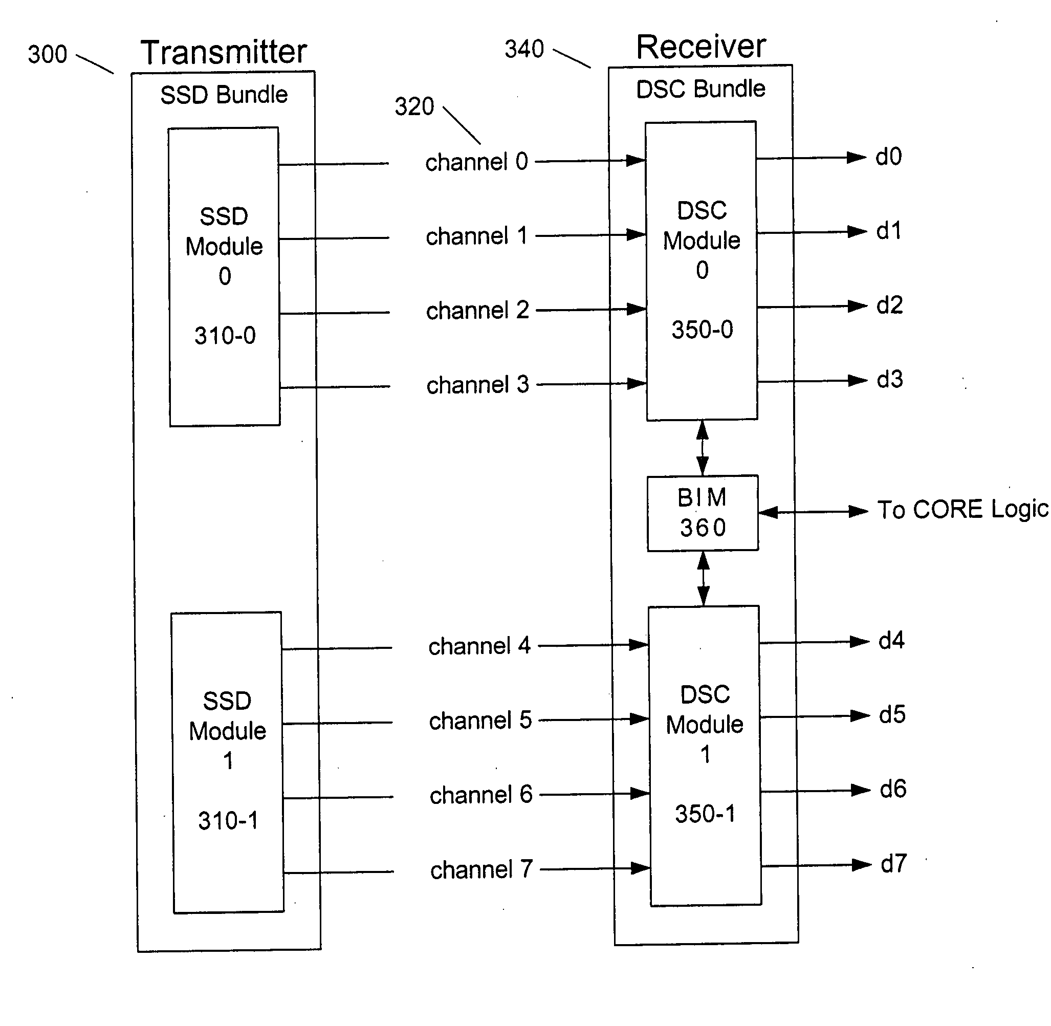
[0062] A preferred embodiment of the deskewing system in accordance with the present invention is shown in FIG. 3. Generally, the link architecture and operation are as follows.

[0063] At a source node, a transmitter 300 comprised of one or more Source Synchronous Driver (SSD) Modules 310-0, 310-1, . . . 310-N drives data onto physical media, for example, optic fiber or copper ribbon cable, forming a parallel bus 320 consisting of a pluralit...


PUM

PropertyMeasurementUnit
timeaaaaaaaaaa
phaseaaaaaaaaaa
zero phase alignmentaaaaaaaaaa

Abstract

A system performs a two-step skew compensation procedure by first correcting for any phase error alignment between a parallel link clock and data signal edges of each data channel, thereby allowing the received data bits to be correctly sampled. Then, a second step is performed to “word-align” the bits into the original format, which is accomplished with a Skew Synchronizing Marker (SSM) byte in a data FIFO of each data channel. The SSM byte is transmitted on each data channel and terminates the skew compensation procedure. When the SSM byte is detected by logic in the data FIFO of each data channel, the data FIFO employs the SSM byte to initialize the read and write pointers to properly align the output data.

Description

FIELD OF THE INVENTION [0001] The present invention relates to high-speed data links and, more particularly, to high-speed parallel data links. Specifically, one embodiment of the present invention provides a system to deskew a high-speed parallel data link. BACKGROUND OF THE INVENTION [0002] As the speed and performance of digital systems increase, demands on interconnects that “link” these systems also increase. “Links” are communications paths between systems, sub-systems, and components enabling them to exchange data. Digital data can be transferred as pulses of electrical energy over electrically conductive material such as metal wires. An alternate technique for conveying digital data is by pulses of light over optic fiber. [0003] Traditionally, serial line protocols employing encoded clock and data have been the protocols of choice for long-haul applications such as WAN (Wide Area Network), LAN (Local Area Network), SAN (Storage Area Network), as well as other proprietary lin...

Claims


Application Information

Patent Timeline
Patent Type & Authority Applications(United States)
IPC IPC(8): G06F11/00G06KH04L7/00G06K1/04G06K5/04G11B5/00G11B20/20H04L25/14
CPCH04L25/14
Inventor COLLINS, HANSEL A.
Owner SYNOPSYS INC
Why Eureka
Try Eureka