Exhaust gas treating apparatus

Inactive Publication Date: 2005-10-20
NGK INSULATORS LTD +2
View PDF4 Cites 35 Cited by
  • Summary
  • Abstract
  • Description
  • Claims
  • Application Information

AI Technical Summary

Benefits of technology

[0011] The present invention was made in consideration of the above-described problems. Accordingly, it is an object of the present invention to provide

Problems solved by technology

As a result, the honeycomb filter 80 may be damaged.
However, with respect to the exhaust gas treatment apparatus in which the oxidation catalyst is placed upstream of the exhaust-gas-inlet-side end surface 83 of the honeycomb filter 80, the temperature required to activate the oxidation catalyst is high, about 400° C.-500° C. Consequently, there are problems in that, for example, when the diesel engine is operated under low-speed and light-load conditions, the temperature of the exhaust system is low.
Therefore, the oxidation catalyst is not activated, and the honeycomb filter 80 cannot be regenerated.
Consequently, there is

Method used


Image

  • Exhaust gas treating apparatus
  • Exhaust gas treating apparatus
  • Exhaust gas treating apparatus

Examples


example 1

(EXAMPLE 1)

[0078] In the present example, as shown in FIG. 6, the exhaust gas treatment apparatus 41 was prepared, in which the honeycomb filter 43 formed by using cordierite having a high electrically-insulating property was placed in the inside of the acrylic resin casing 2 for serving as a main flow path of an exhaust gas in such a manner that interrupts this main flow path, and the stainless steel pulse electrode 44 having a mesh size of 2.6 mm×2.6 mm and the fluororesin-coated stainless steel earth electrode 45 having a mesh size of 2.6 mm×2.6 mm were placed on opposite outer perimeter surfaces of this honeycomb filter 43.

[0079] With respect to the shape of the honeycomb filter 43, the length in the direction of the flow of the exhaust gas was 152 mm, the end surfaces were quadrangular prism of 48 mm in width×24 mm in height, the cell density was 16 cells / cm2, and the thickness of the partition walls was 0.43 mm, while the honeycomb filter 43 was formed by extrusion with a met...

example 2

(EXAMPLE 2)

[0087] In the present example, an exhaust gas treatment apparatus similar to that in FIG. 10 was prepared, in which a honeycomb filter formed by using cordierite having a high electrically-insulating property was placed in the inside of a quartz glass casing for serving as a main flow path of an exhaust gas in such a manner that interrupts this main flow path, and a pulse electrode and an earth electrode were placed, the pulse electrode having a configuration in which a plurality of stainless steel needles of 7 mm in length were placed on a net-shaped stainless steel plate at a distance of 8 mm from each end surface of this honeycomb filter. In the present example, 4.1 g / L of soot was deposited in the honeycomb filter, and the mass of the honeycomb filter was 55.2525 g.

[0088] A measurement flow and measurement apparatus configured similarly to those shown in FIG. 11 were used. A NO mixture gas adjusted to have a NO concentration of 320 ppm was introduced at a flow rate o...


PUM

PropertyMeasurementUnit
Electric potential / voltageaaaaaaaaaa
Frequencyaaaaaaaaaa

Abstract

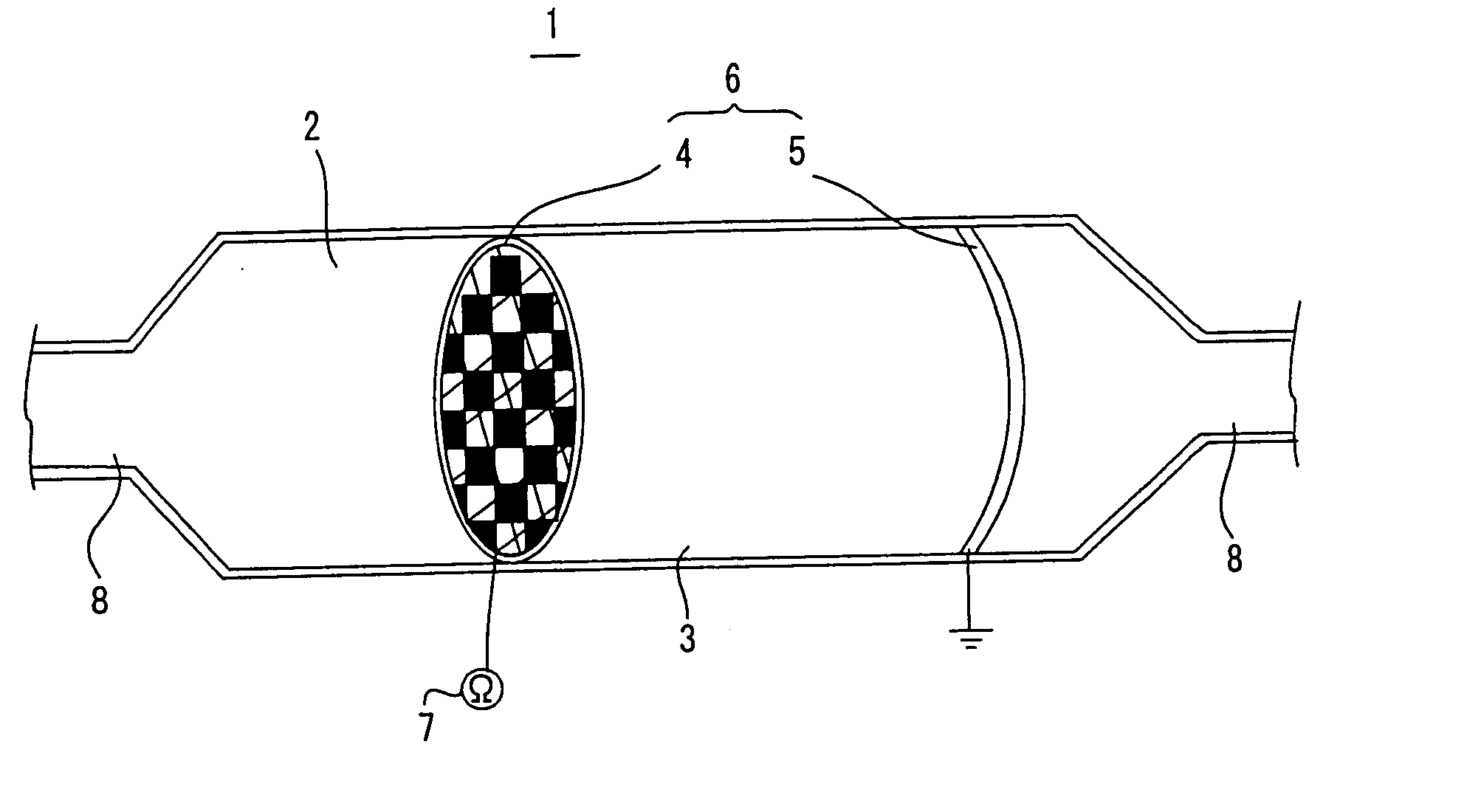
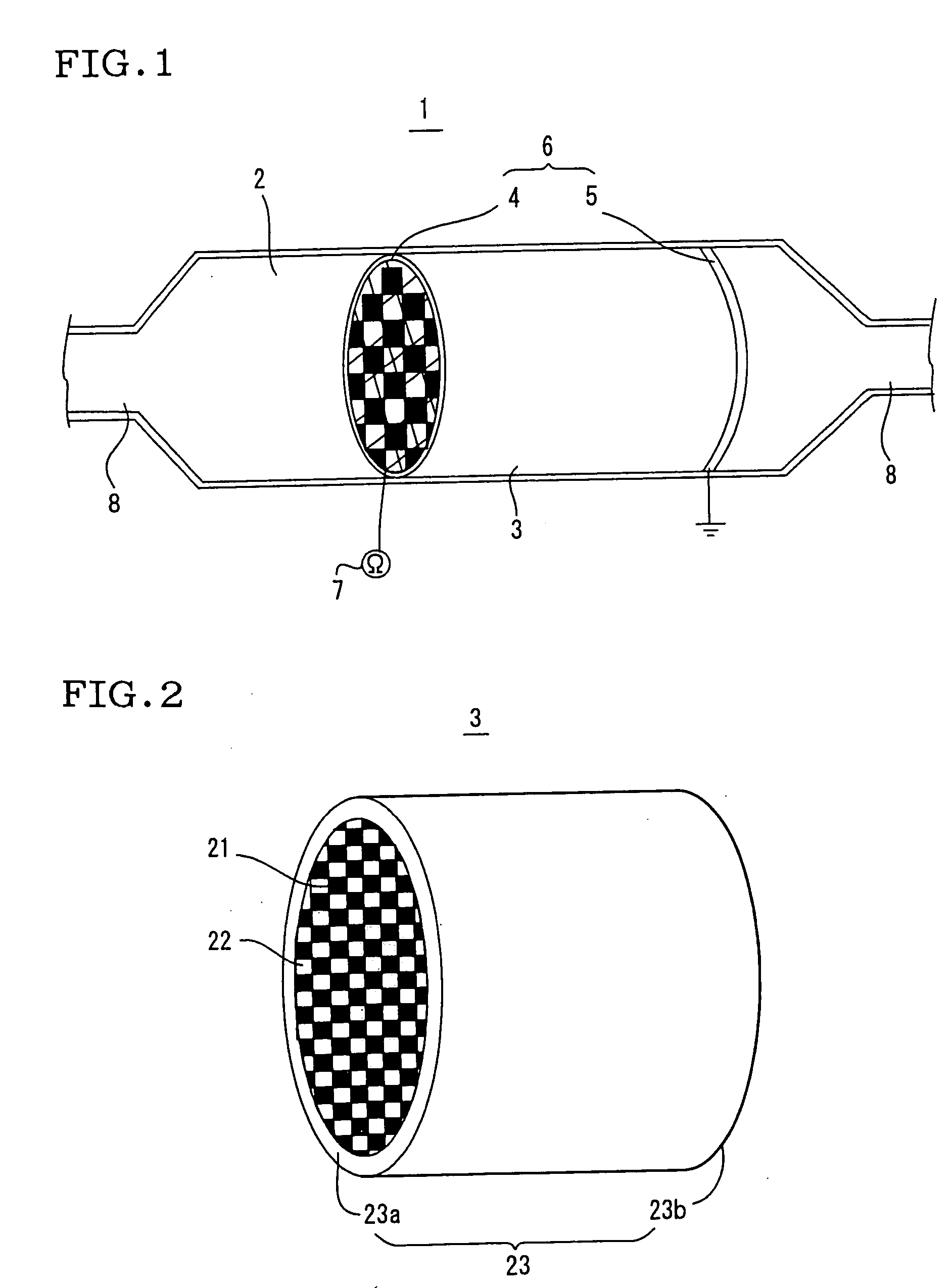
The present invention is characterized in that a casing 2 connected to an exhaust system 8, a honeycomb filter 3 placed in the inside of the casing 2, the honeycomb filter having a plurality of cells partitioned by partition walls, and plasma generation electrodes 6 placed being faced each other by sandwiching the honeycomb filter there are included, particulate matter contained in an exhaust gas is collected by the honeycomb filter 3, nitrogen monoxide contained in the exhaust gas is oxidized to nitrogen dioxide by nonthermal plasma generated between a pulse electrode 4 and an earth electrode 5 constituting the plasma generation electrodes 6, combustible materials in the particulate matter collected and deposited on the surface of the partition walls are removed through oxidation by the nitrogen dioxide produced. As a result, the honeycomb filter 3 can be regenerated.

Description

TECHNICAL FIELD [0001] The present invention relates to an exhaust gas treatment apparatus. In particular, the present invention relates to an exhaust gas treatment apparatus capable of highly precisely collecting particulate matter contained in an exhaust gas with a honeycomb filter, removing combustible materials in the collected particulate matter simply by oxidation at low energy, and regenerating the honeycomb filter. In addition, the exhaust gas treatment apparatus can be miniaturized compared with a known exhaust gas treatment apparatus through the use of nonthermal plasma. BACKGROUND ART [0002] As regulations on exhaust gases are stepped up in emission of combustion gases generated from heat engines, e.g., internal combustion engines, or combustion apparatus, e.g., boilers, through exhaust systems, improvements are performed on the incineration of engines, for example, compositions of fuels are improved. On the other hand, exhaust gases emitted from the above-described inter...

Claims


Application Information

Patent Timeline
IPC IPC(8): B01D46/00B01D46/42B01D53/32B01D53/56B01D53/74B01D53/94B01J19/08F01N3/00F01N3/01F01N3/02F01N3/022F01N3/023F01N3/025F01N3/027F01N3/029F01N3/033F01N3/035F01N3/08F01N3/20F01N3/28F01N13/02F01N13/04H05H1/24
CPCB01D53/32F01N13/009B01D2258/01B01D2259/818F01N3/005F01N3/02F01N3/0222F01N3/023F01N3/0231F01N3/033F01N3/0814F01N3/0892F01N2240/28F01N2330/06F01N2330/48F01N2570/14F01N2610/02H05H1/24Y10S55/30Y10S55/10F01N13/017F01N13/0097B01D53/9431B03C3/06B03C3/155B03C3/41B03C3/49B03C2201/30H05H1/2406H05H2245/17
Inventor OKUBO, MASAAKIYAMAMOTO, TOSHIAKIMIWA, SHINICHI
Owner NGK INSULATORS LTD
Why Eureka
Try Eureka