
Parking mechanism for transmission

Inactive Publication Date: 2005-10-20
NISSAN MOTOR CO LTD
View PDF9 Cites 18 Cited by
  • Summary
  • Abstract
  • Description
  • Claims
  • Application Information

AI Technical Summary

Benefits of technology

[0006] To avoid this, it is possible to improve the durability and reliability of the hydraulic system and electronic system or to add an additional parking mechanism. However, the measures would increase the complexity of the system, increase the size of the system or increase the cost. It is therefore an object of the present invention to provide a simple, reliable and compact parking mechanism.

Problems solved by technology

Therefore, if the transmission system becomes unable to supply the oil pressure over the pressing force because of failure in the hydraulic system or the electronic control system during a vehicle running operation at one of the speeds obtained through the second automatic clutch provided with no elastic member, the first clutch is engaged by the elastic member, the elastic member presses the first clutch to engagement, and as a result, both the first and second clutches are engaged simultaneously, so that the gear mechanism might be damaged by simultaneous engagement of two different speeds.
Moreover, if the first automatic clutch is engaged suddenly by the elastic member while the vehicle is held at rest with the engine in operation, the vehicle might be started suddenly.
However, the measures would increase the complexity of the system, increase the size of the system or increase the cost.

Method used


Image

  • Parking mechanism for transmission
  • Parking mechanism for transmission
  • Parking mechanism for transmission

Examples


first embodiment

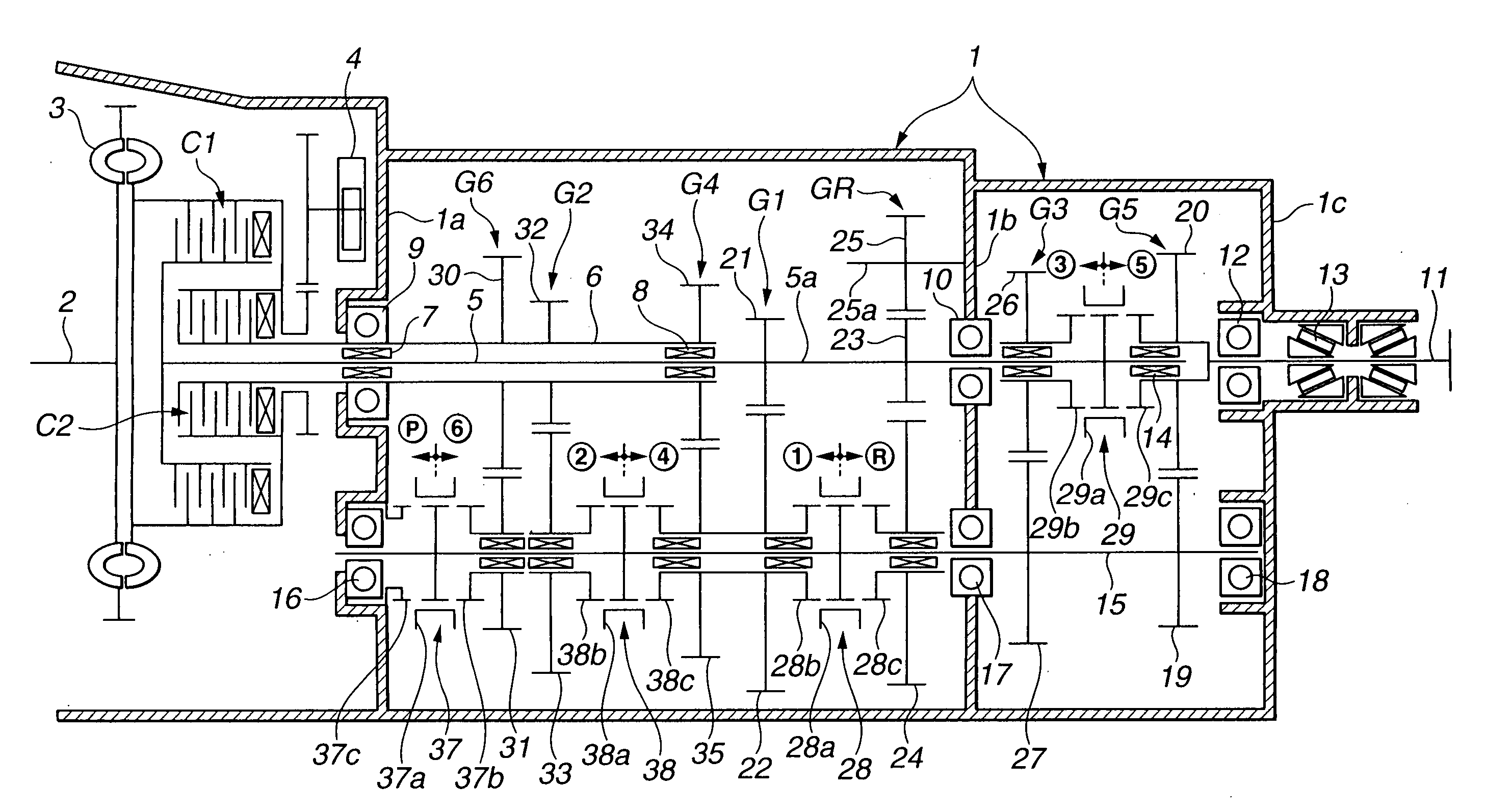
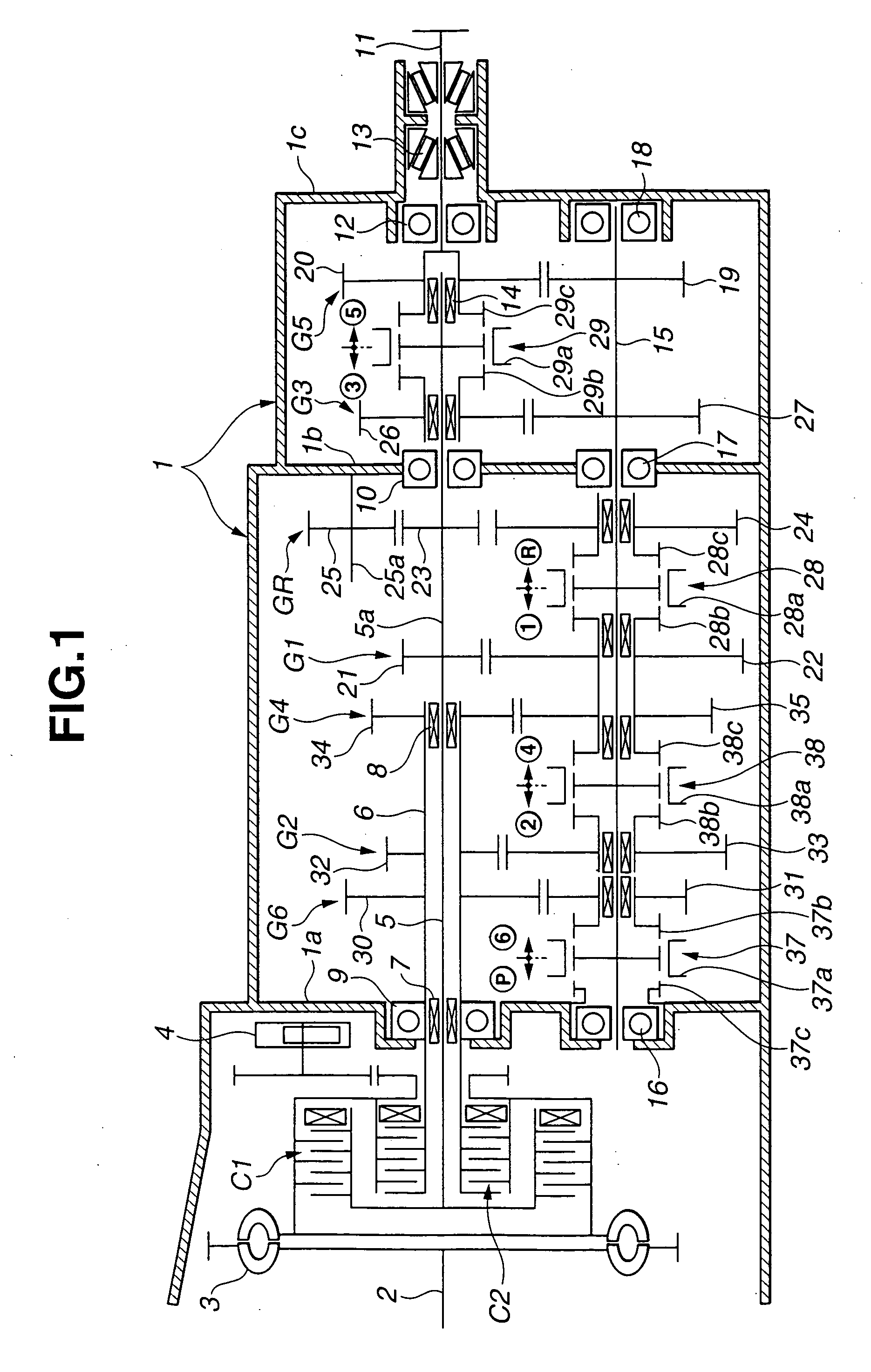
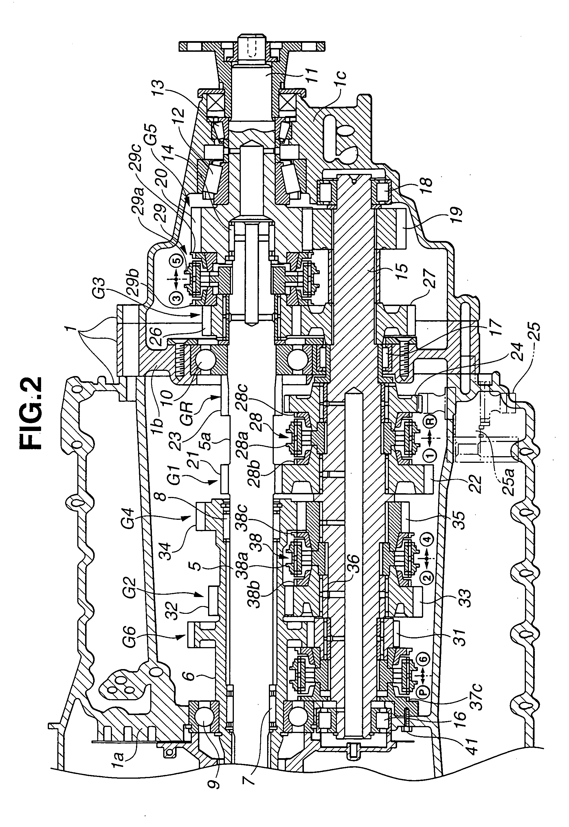
[0012]FIGS. 1 and 2 show a twin-clutch, meshing type automatic transmission according to the present invention. This automatic transmission is suitable for a front engine, rear wheel drive ve4hicle (FR vehicle).

[0013] As shown in FIG. 1, between a crankshaft 2 of an engine and a gear transmission mechanism enclosed in a transmission case 1, there are provided two automatic clutches C1 and C2. In this example, the first automatic clutch C1 is for gear speeds of odd numbers (first speed, third speed, fifth speed and reverse); and the second automatic clutch C2 is for gear speeds of even numbers (second speed, fourth speed and sixth speed). First and second clutches C1 and C2 are connected through a torsional damper 3, with the engine crankshaft 2. In transmission case 1, there is further provided an oil pump 4 which is always driven by the engine through torsional damper 4. The operating oil discharged from oil pump 4 is used for the gear speed selection control including the control ...

second embodiment

[0061] The thus-constructed single-clutch meshing type transmission according to the present invention is operated as follows:

[0062] In the neutral (N) range, clutch C is engaged, but all the coupling sleeves 128a, 129a, 137a and 138a of the four synchromesh mechanisms 128, 129, 137 and 138 are put at the neutral position, so that the transmission is in the neutral state incapable of transmitting torque.

[0063] To select the first speed in D range: the transmission system disengages clutch C; connects first speed output gear 122 with counter shaft 115 by shifting coupling 128a of synchromesh mechanism 128 leftwards; and then engages clutch C. Therefore, the engine rotation from clutch C is transmitted through input shaft 100, first speed gear set G1, counter shaft 115, to output shaft 111, and the first speed is attained. Clutch C is controlled in a start control mode when the first speed is used for starting the vehicle.

[0064] For upshift from first speed to second speed: the tran...


PUM


Abstract

An automatic transmission includes a transmission case, a parking gear fixed to the transmission case, and a meshing mechanism, such as a synchromesh mechanism. The meshing mechanism includes a coupling sleeve to engage with the parking gear and hold a transmission output member unrotatable in a park lock state when the coupling sleeve is shifted axially toward the parking gear.

Description

BACKGROUND OF THE INVENTION [0001] The present invention relates to a parking mechanism of a transmission for a vehicle, and specifically to a parking mechanism of an automated manual transmission. [0002] A meshing type automatic transmission constructed to automate driver's manual operations for an ordinary manual transmission is in practical use. One example is a twin-clutch type automatic transmission including first and second input shafts to be connected with an engine through respective automatic clutches. [0003] A U.S. Pat. No. 5,711,409 (specifically column 12, lines 32-50, FIG. 10)(corresponding to P8004788) shows a parking system for such a twin-clutch automatic transmission in which a Park function for parking lock is attained by a pressing force of an elastic member applied to a pressure plate of one of the automatic clutches, and by selecting one of the gear speed associated with that automatic clutch. SUMMARY OF THE INVENTION [0004] The parking system of the above-ment...

Claims


Application Information

Patent Timeline
IPC IPC(8): B60T1/06F16H3/00F16H3/08F16H63/34F16H63/48
CPCF16H3/006F16H63/48F16H2061/047Y10T74/19219Y10T74/19288Y10T74/194Y10T74/19242F16H63/3441
Inventor HARA, TOMOYUKI
Owner NISSAN MOTOR CO LTD
Learn More