Epi-illumination microscope and fluorescence filter set

a fluorescence filter set and microscope technology, applied in the field of epi-illumination microscopes, can solve the problems of generating noise, limiting the thin-film design, and limiting the broadening of the reflection band, and achieve the effect of efficient reflection

Active Publication Date: 2005-10-20
EVIDENT CORP
View PDF17 Cites 17 Cited by
  • Summary
  • Abstract
  • Description
  • Claims
  • Application Information

AI Technical Summary

Benefits of technology

[0016] A second aspect of the present invention is directed to a fluorescence filter set. The fluorescence filter set of the present invention comprises a first wavelength selection member that selectively transmits exciting light; a light splitter that reflects the exciting light from the first wavelength selection member to epi-illuminate a sample and transmits fluorescence emitted from the sample; and a second wavelength selection member that selectively transmits the fluorescence transmitted thro

Problems solved by technology

Therefore, unlike the transmission bands of the excitation filter (first selection member) and the absorption filter (second selection member), there is a limitation on thin-film design in bringing the transmission wavelength band close to a reflection wavelength band.
However, a conventional light splitter has a constitution in which one face of the transparent substrate is coated with a dichroic mirror having an only stacked portion fo

Method used


Image

  • Epi-illumination microscope and fluorescence filter set
  • Epi-illumination microscope and fluorescence filter set
  • Epi-illumination microscope and fluorescence filter set

Examples


first embodiment

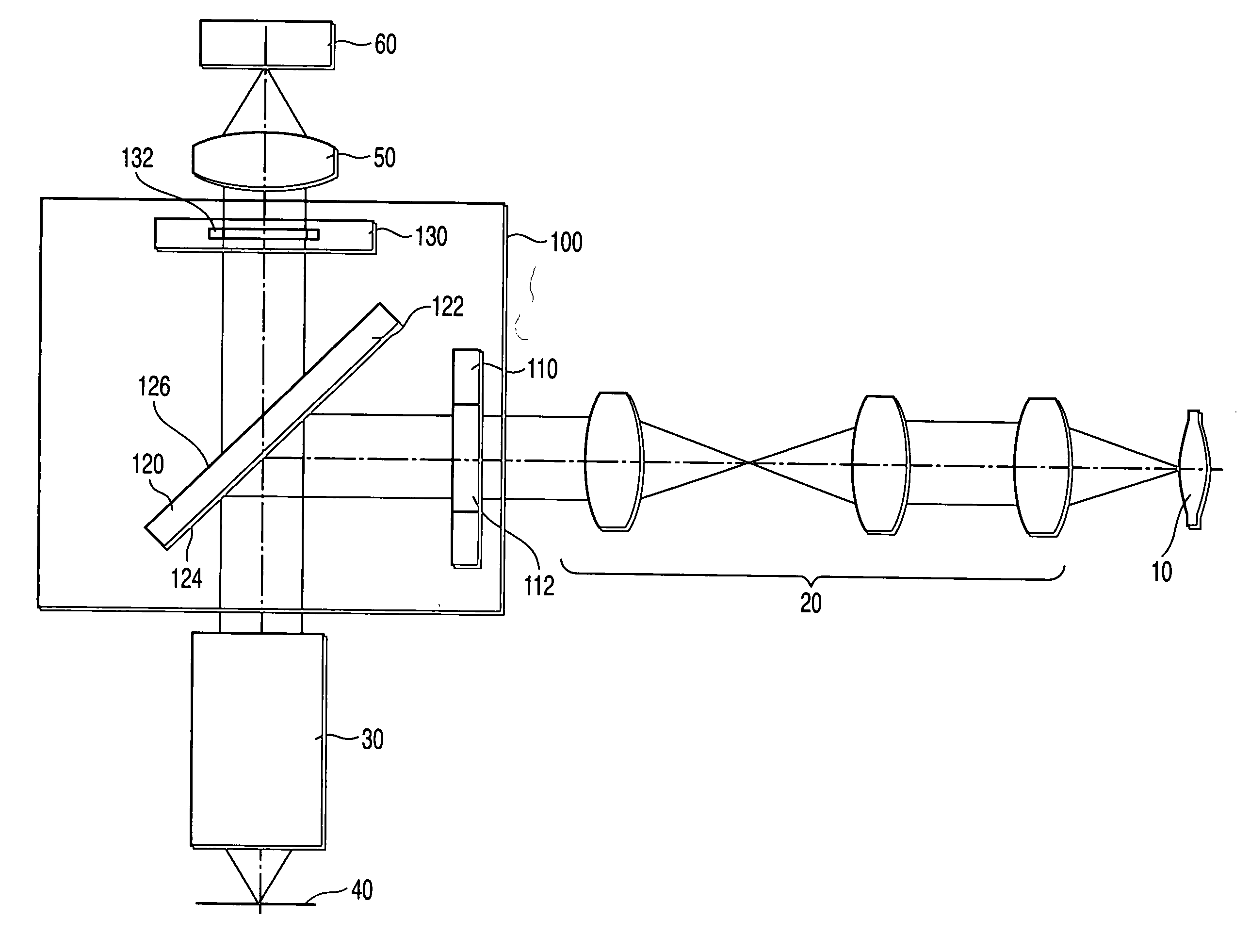
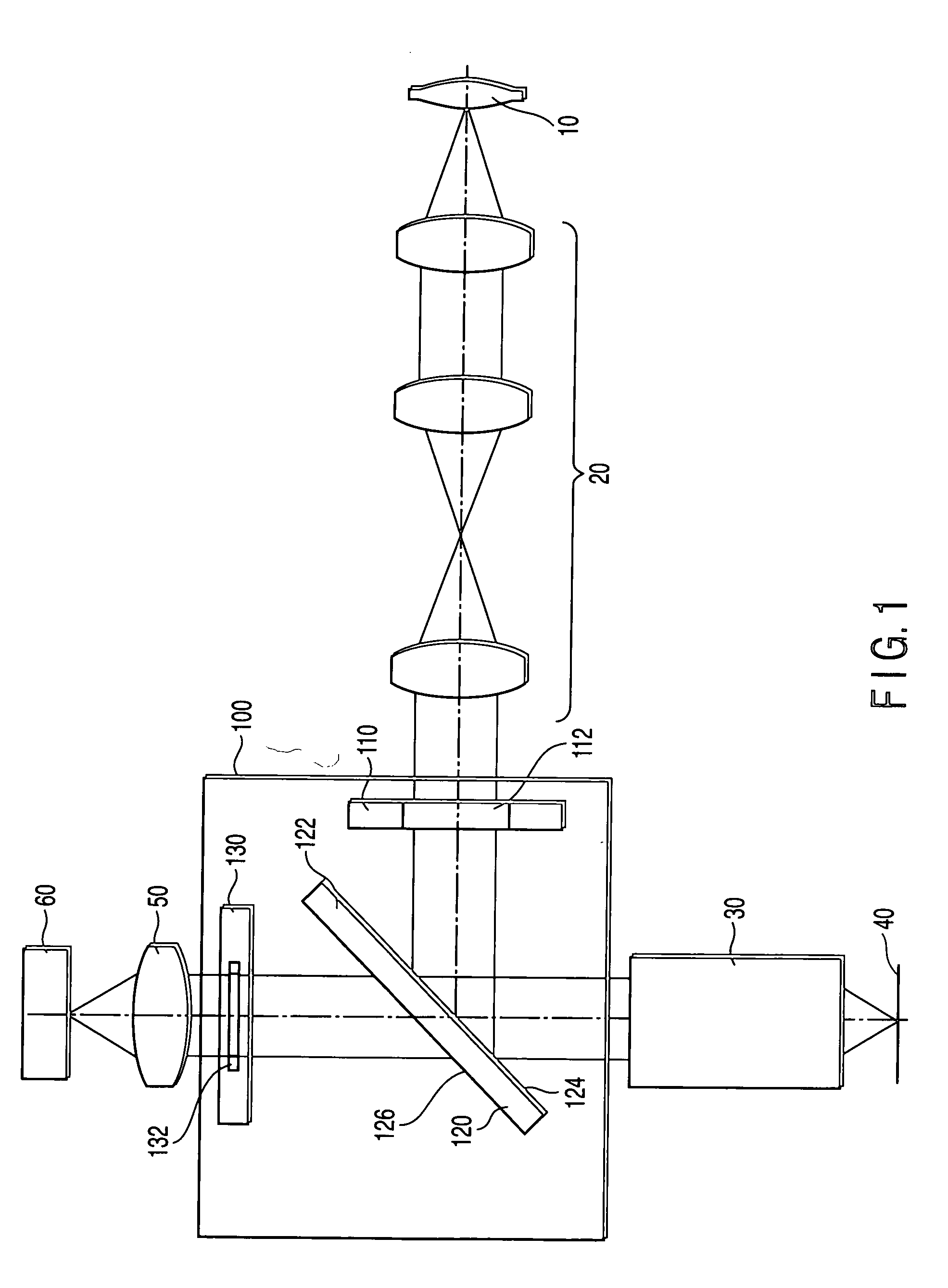
[0042] The present embodiment relates to an upright microscope. FIG. 1 shows a constitution of a microscope according to a first embodiment of the present invention. As shown in FIG. 1, the microscope comprises a light source 10, an optical illumination system 20, a fluorescence filter set 100, an objective lens 30, an image forming lens 50, and a detection device 60.

[0043] The objective lens 30, image forming lens 50, and detection device 60 constitute an optical observation system that observes a sample 40. The light source 10, which is located off an optical axis of the optical observation system, emits light for illuminating the sample 40. The light source 10 is not limited to this, and comprises, for example, a mercury lamp.

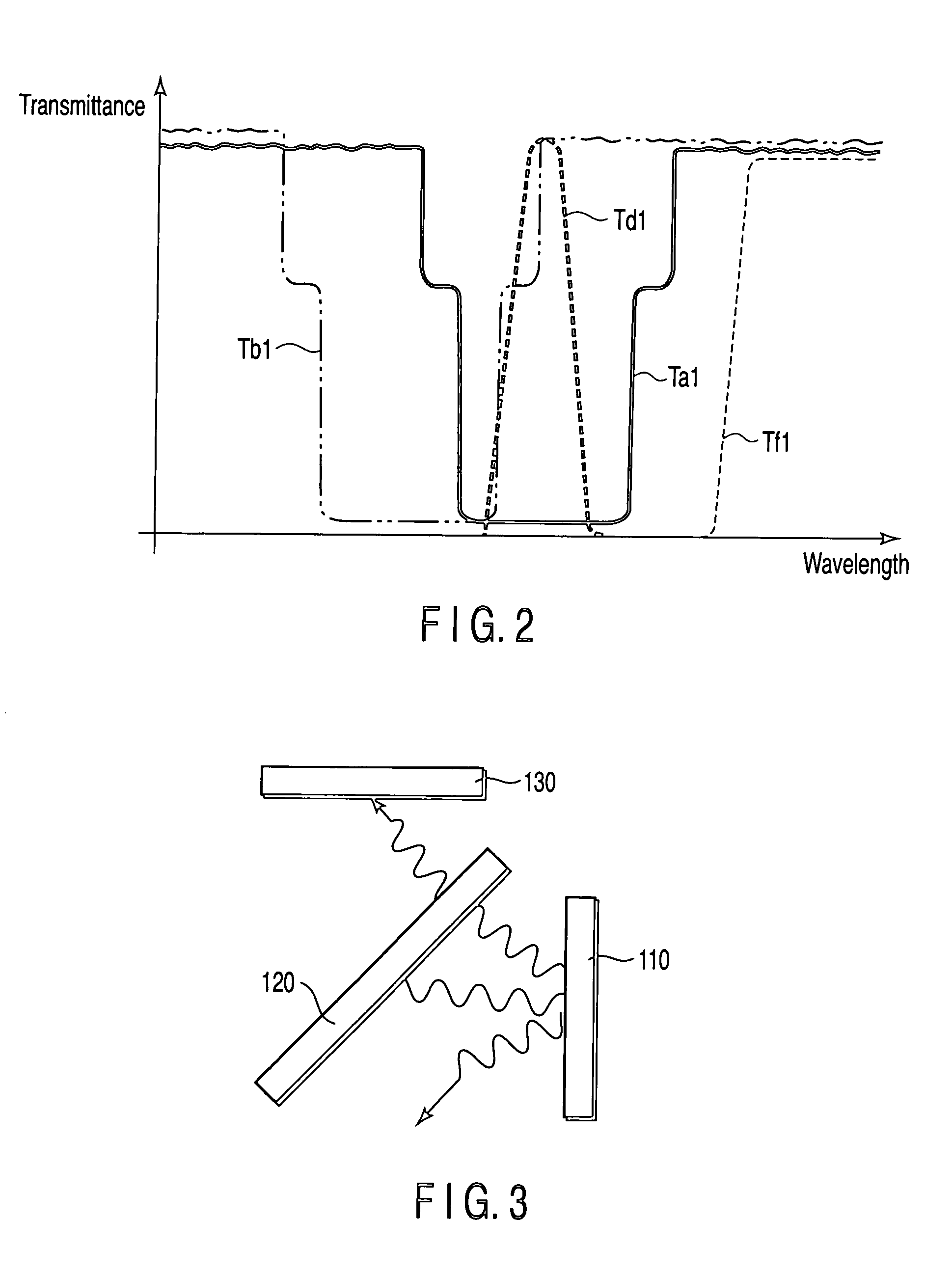
[0044] The fluorescence filter set 100 comprises a first wavelength selection member 110, a light splitter 120, and a second wavelength selection member 130. The first wavelength selection member 110 functions as an excitation filter, and the second wavele...

second embodiment

[0079] A whole constitution of an epi-illumination microscope according to a second embodiment of the present invention is substantially the same as that of the first embodiment, and is therefore as shown in FIG. 1. However, the light splitter 120 of the present embodiment is different from that of the first embodiment in that a dichroic mirror coat 124 is disposed on the front surface of a flat-plate-like transparent substrate 122, and a reflection preventive film 126 is disposed on the back surface.

[0080] The dichroic mirror coat on the front surface is preferably formed by stacked layers of a high-refractive-index material having a refractive index of 2.0 or more and a low-refractive-index material having a refractive index of 1.5 or less in the same manner as in the dichroic mirror coat in the first embodiment. Among the materials, the coat comprises a stacked layer that efficiently reflects the light having the wavelength selected by the first wavelength selection member 110, ...

third embodiment

[0098] A whole constitution of an epi-illumination microscope according to a third embodiment of the present invention is substantially the same as that of the first embodiment, and is therefore as shown in FIG. 1. However, in the present embodiment, spectral characteristics of a first dichroic mirror coat 124 and a second dichroic mirror coat 126 of a light splitter 120 are different from those of the first embodiment. In the present embodiment, the first dichroic mirror coat 124 and the second dichroic mirror coat 126 have spectral characteristics that substantially the same band is reflected, and substantially the same band is transmitted.

[0099] That is, the second dichroic mirror coat 126 reflects light of substantially the same wavelength band as that of a reflection band of the first dichroic mirror coat 124. Furthermore, the first dichroic mirror coat 124 and the second dichroic mirror coat 126 transmit fluorescence emitted from the sample.

[0100] In the light splitter 120 o...


PUM


Abstract

A microscope has a light source that emits light to illuminate a sample, a first wavelength selection member that selectively transmits the light from the light source, a light splitter that reflects the light from the first wavelength selection member to epi-illuminate the sample and transmits the light emitted from the sample, and a second wavelength selection member that selectively transmits the light transmitted through the light splitter. The light splitter is constituted of a transparent member and a dichroic mirror coat disposed on the transparent member. The dichroic mirror coat is constituted of a stacked layer that efficiently reflects light having a wavelength selected by the first wavelength selection member and a stacked layer that reflects light on a short wavelength side from the light selected by the first wavelength selection member, light on a long wavelength side, light of the same band, or combined light.

Description

CROSS-REFERENCE TO RELATED APPLICATIONS [0001] This application is based upon and claims the benefit of priority from prior Japanese Patent Applications No. 2004-111356, filed Apr. 5, 2004; and No. 2004-355747, filed Dec. 8, 2004, the entire contents of both of which are incorporated herein by reference. BACKGROUND OF THE INVENTION [0002] 1. Field of the Invention [0003] The present invention relates to an epi-illumination microscope for use in observing light emitted from a sample. [0004] 2. Description of the Related Art [0005] In general, a fluorescence observing epi-illumination microscope has been used for detecting fluorescence-labeled protein, tissue, gene and the like on a biological tissue cell in a biological or medical field. Especially, in recent years, a research of a micro sample having a level of one molecule that emits only feeble fluorescence, or a research using a living sample, not a fixed sample has been vigorously performed. Additionally, it is possible to devel...

Claims


Application Information

Patent Timeline
IPC IPC(8): G02B21/16G01J3/30G01N21/64G02B21/00G02B21/06G02B21/08
CPCG01N21/6456G01N21/6458G02B21/16G02B21/082G01N21/6486
Inventor HORIGOME, SHUHEIWATANABE, TADASHI
Owner EVIDENT CORP
Why Eureka
Try Eureka