Device for the amplification of dna, comprising a microwave energy source

a technology of amplification device and dna, which is applied in the direction of biochemistry apparatus, biochemical equipment and processes, centrifuges, etc., can solve the problems of inability to determine optimal temperature and time for each stage, inability to instantaneous temperature changes, and time is still too long for linear amplification process us

Inactive Publication Date: 2005-10-20
CORBETT LIFE SCI
View PDF8 Cites 35 Cited by
  • Summary
  • Abstract
  • Description
  • Claims
  • Application Information

AI Technical Summary

Benefits of technology

[0048] The device according to the invention allows a reaction vessel to be held with its wall at typically 50-65° C. with energy for the denaturation being supplied to the reaction mixture by energizing the magnetron (typically for several seconds). As the reaction vessel wall is held at the typical annealing temperature of 50-65° C., the mixture returns to that temperature shortly after application of microwave energy is terminated due to the fact that the reaction vessel does not absorb an appreciable amount of microwave energy. This reduces the cycle time to ...

Problems solved by technology

Extended amplification times of two to four hours are common and long transition times make it difficult to determine optimal temperatures and times for each stage.
Instantaneous temperature changes are not possible because of sample, container and cycler heat capacities.
Whi...

Method used


Image

  • Device for the amplification of dna, comprising a microwave energy source

Examples


Embodiment Construction

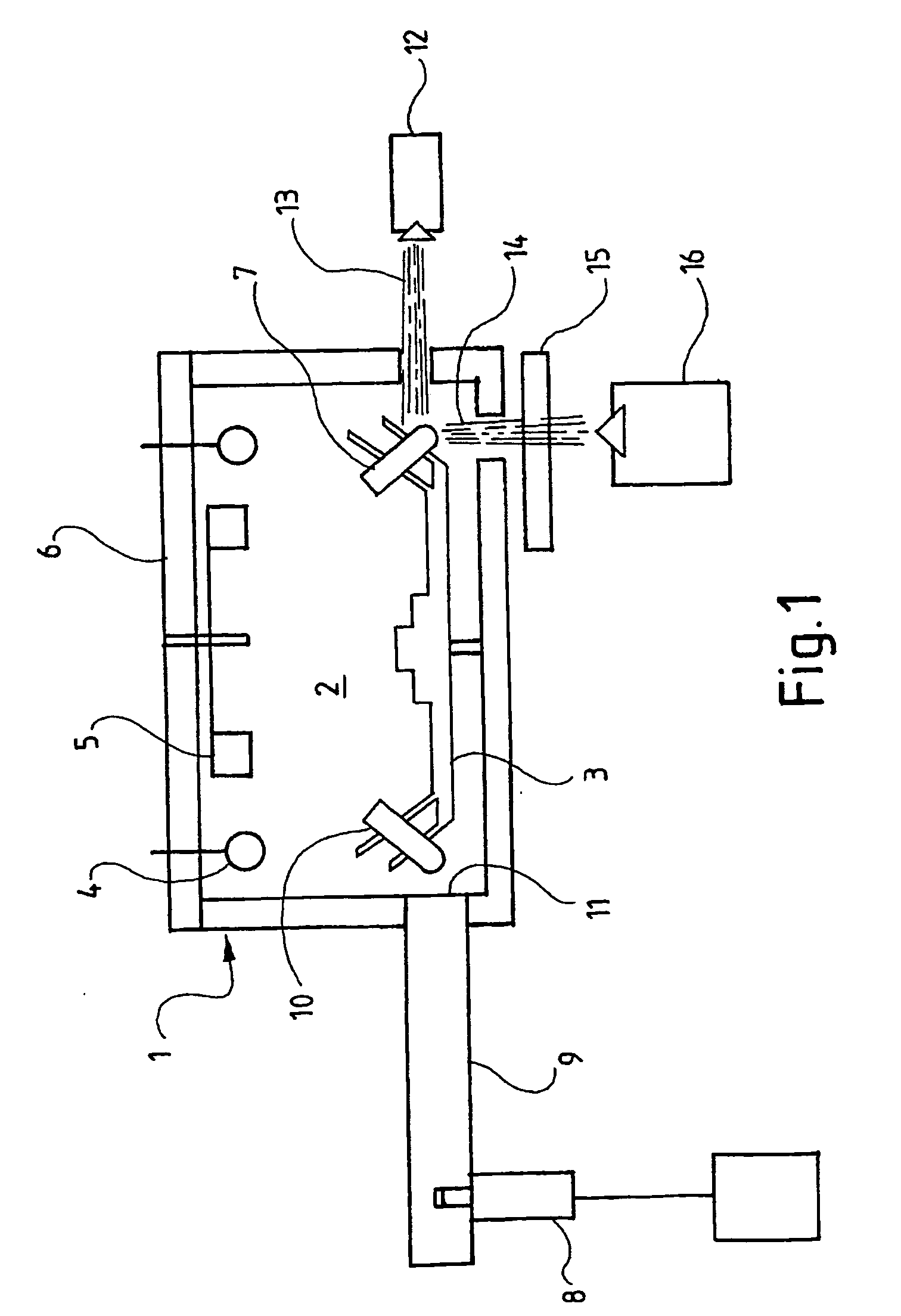
[0052] With reference to FIG. 1, device 1 comprises a chamber 2 having rotor 3 which is driven by a stepper motor not shown in the drawing. Chamber 2 also includes a radial heater 4 and a fan 5 for distributing heated air throughout the chamber. Heater 4 and fan 5 are mounted to hinged lid 6 of the device, which lid can be pivoted out of the way to gain access to rotor 3. Rotor 3 has a plurality of holes for holding reaction vessels, one of which vessels is item 7.

[0053] Device 1 also includes a magnetron 8 from which microwaves can be directed via wave-guide 9 to reaction vessels such as 10 as they pass the microwave emission point 11. A light source 12 is provided for illuminating a reaction vessel as it passes through beam 13. Light 14 emitted from reaction vessel 7 passes through filter 15 to be detected by photomultiplier tube 16.

[0054] Device components such as the rotor drive, heater 4, fan 5, magnetron 8, and light source 12, are controlled by a computer not shown in the d...


PUM

PropertyMeasurementUnit
Temperatureaaaaaaaaaa
Denaturation enthalpyaaaaaaaaaa
Energyaaaaaaaaaa

Abstract

The invention relates to a device for the amplification of DNA in a reaction mixture, the device (1) comprising a heated chamber (2) including a rotor (3) for holding a plurality of reaction vessels for reaction mixtures, a drive means for the rotor, a microwave energy source (8) with means for controlled delivery of said energy to the reaction mixtures, and a system (14-16) for determining denaturation of double-stranded DNA. The invention also provides a method for the amplification of a nucleic acid strand. In the first step of the method, a reaction mixture is formed comprising the target nucleic acid strand, nucleotides, a primer, a thermostable nucleic acid polymerase, and, if necessary, a reagent for the detection of denaturation of double-stranded DNA. In the second step, the mixture is incubated at a temperature which allows synthesis of a nucleic acid strand complementary to the target nucleic acid strand. The third step comprises denaturing double-stranded DNA formed in the second step by microwave energisation of the reaction mixture with monitoring of the mixture to determine the denaturation end point. The reaction mixture is allowed to cool to a temperature at which primer anneals to the target nucleic acid strand in the fourth step. The second to fourth steps are repeated until a desired level of amplification is achieved.

Description

TECHNICAL FIELD [0001] The invention the subject of this application relates to procedures that require the rapid cycling of a reaction mixture between different conditions. More particularly, the invention relates to a device and method for use in such cycling procedures. The device and method are particularly suited for amplifying DNA in processes involving successive cycles of annealing, polymerisation and denaturation steps. BACKGROUND ART [0002] In a number of applications such as gene analysis and DNA profiling, it is desirable to multiply the amount of particular nucleic acid sequences present in a sample. For example, a duplex DNA segment of up to approximately six thousand base pairs in length may be amplified many million fold by means of the polymerase chain reaction (PCR), starting from as little as a single copy. In this technique, a denatured duplex DNA sample is incubated with a molar excess of two oligonucleotide primers, one being complementary to a short strand of ...

Claims


Application Information

Patent Timeline
IPC IPC(8): B01L7/00B04B15/02C12Q1/68C12Q1/6816C12Q1/686
CPCB01L7/52B01L7/5255G01N2035/0444G01N2035/00405C12Q1/686C12Q1/6816B01L2200/147B01L2300/0627B01L2300/0803B01L2300/1844B01L2300/1866B04B15/02C12Q2563/173C12Q2523/313
Inventor CORBETT, JOHN MICHAELCORBETT JR, JOHN MICHAEL
Owner CORBETT LIFE SCI
Why Eureka
Try Eureka