Heat exchanger

a technology of heat exchanger and heat exchanger body, which is applied in the direction of indirect heat exchanger, lighting and heating apparatus, coatings, etc., can solve the problems of difficult to improve heat exchange performance, reduce the operation efficiency of the fuel reforming system, and achieve the effect of increasing heat exchange efficiency, and reducing the cost of heat exchang

Inactive Publication Date: 2005-10-27
HONDA MOTOR CO LTD
View PDF7 Cites 52 Cited by
  • Summary
  • Abstract
  • Description
  • Claims
  • Application Information

AI Technical Summary

Benefits of technology

[0013] In the above heat exchanger, the three fluids may preferably, but not necessarily, be such that a heat capacity of the second fluid is greater than those of the first and third fluids. Moreover, it may be preferable that a temperature of the first fluid is higher than a temperature of the second fluid, and a temperature of the third fluid is higher than the temperature of the second fluid. Instead, it may also be preferable that a temperature of the first fluid is higher than a temperature of the second fluid, and the temperature of the second fluid is higher than a temperature of the third fluid. Particular combinations of the fluids selected in accordance with the above-specified criteria would increase the efficiency in heat exchange, thereby allowing the second fluid to cool or heat the first and third fluids more effectively.
[0014] In cases where the above heat exchanger is provided in combination with a fuel reforming system in which hydrogen is obtained from hydrocarbon feedstocks in a steam reforming process, the combination of the fluids applied therein may be such that the first fluid a reformed gas generated in a reformer, the second fluid is a coolant, and the third fluid is compressed air generated in a compressor. This heat exchanger would allow the coolant to cool the reformed gas and the compressed air more effectively. Alternatively, the combination may be such that the first fluid is a reformed gas generated in a reformer, the second fluid is a steam fuel mixture, and the third fluid is an exhaust gas. This heat exchanger would make the cooling of the reformed gas and the heating of the steam fuel mixture more efficiently.

Problems solved by technology

Since the above-described integrated heat exchangers are each designed to form a single unit by simply combining two or more heat exchangers together, heat exchange among three or more fluids could not be achieved in the single-unit heat exchangers without increasing the heat exchange volume.
In this configuration, a plurality of pipes through which the reformed gas is flowed are disposed within a cylindrical container in which the coolant is flowed, which would increase the amount of the coolant existing in the heat exchanger and would thus require an extended period of time for warming up of the fuel reforming system, disadvantageously decreasing the operation efficiency of the fuel reforming system.
Moreover, in this type of the heat exchanger, the cylindrical container would inevitably be large in volume, which would make it difficult to improve the heat exchange performance by increasing the flow rate of the coolant flowed in the cylindrical container.
It could be conceivable that the flow rate of the coolant would be increased by providing baffle plates spaced at small spacings in the cylindrical container, but this would increase the pressure loss of the coolant in the cylindrical container, thus causing disadvantageous increase in the load and power consumption of the circulating pump.
This type of the integrated heat exchanger however has the following disadvantages in production process and in reliability of the product.
Moreover, the multilayer structure of this heat exchanger is produced by bonding the alternately stacked porous thermally conductive boards and thermally insulating boards with the adhesive sheets, and thus could hardly avoid incomplete bonding which would entail leakage and / or mixture of the fluids, or other undesirable consequences.
To be more specific, there is a potential of peeling or the like as a result of degradation of the adhesive which would progress as the laminated body carries high-temperature fluids over a long period of time.

Method used


Image

  • Heat exchanger
  • Heat exchanger
  • Heat exchanger

Examples


first embodiment

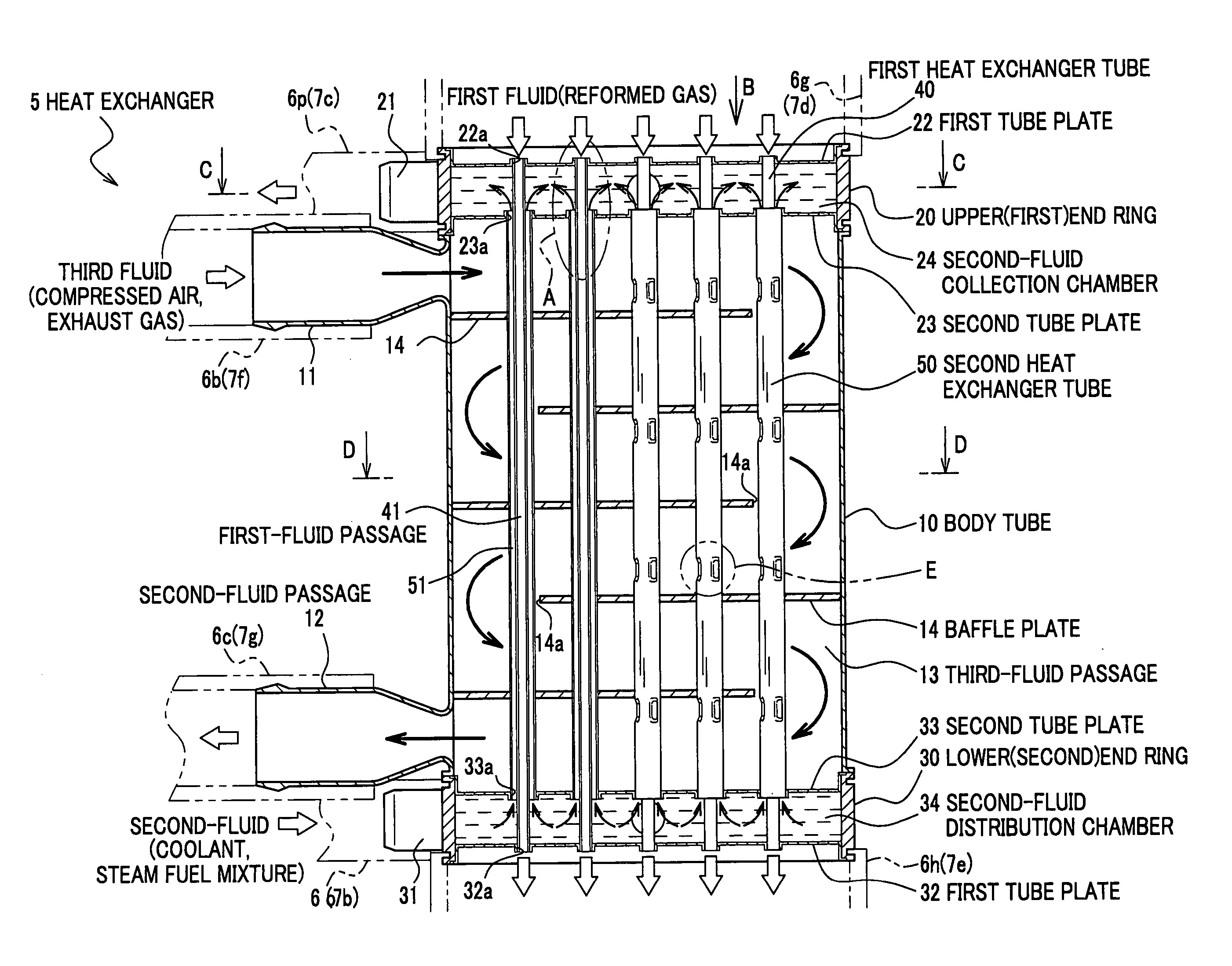
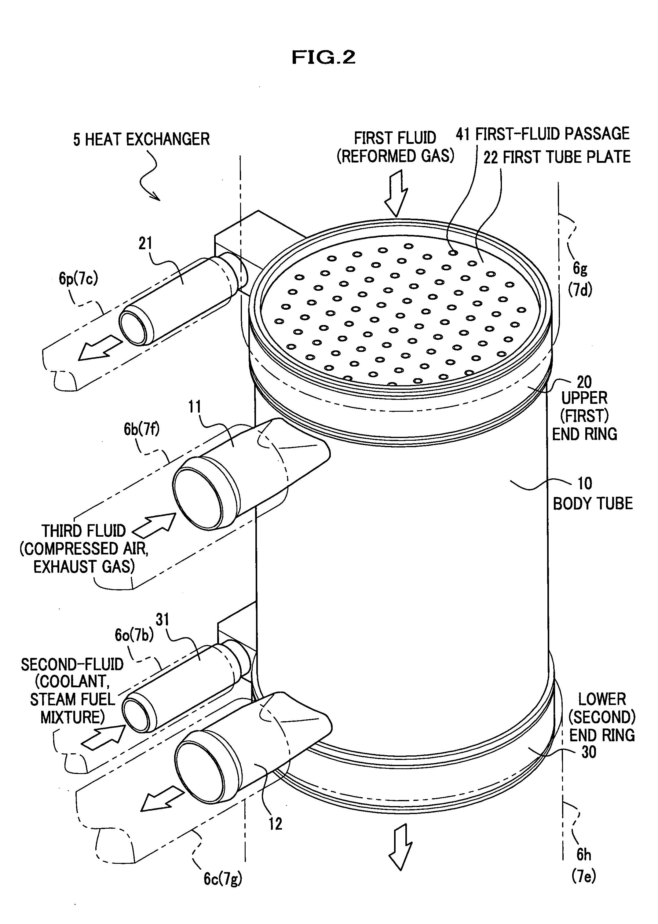
[0031] A detailed description will be given of a heat exchanger according to a first embodiment of the present invention with reference to FIGS. 1 through 10, in which the heat exchanger is provided in two types of fuel reforming systems.

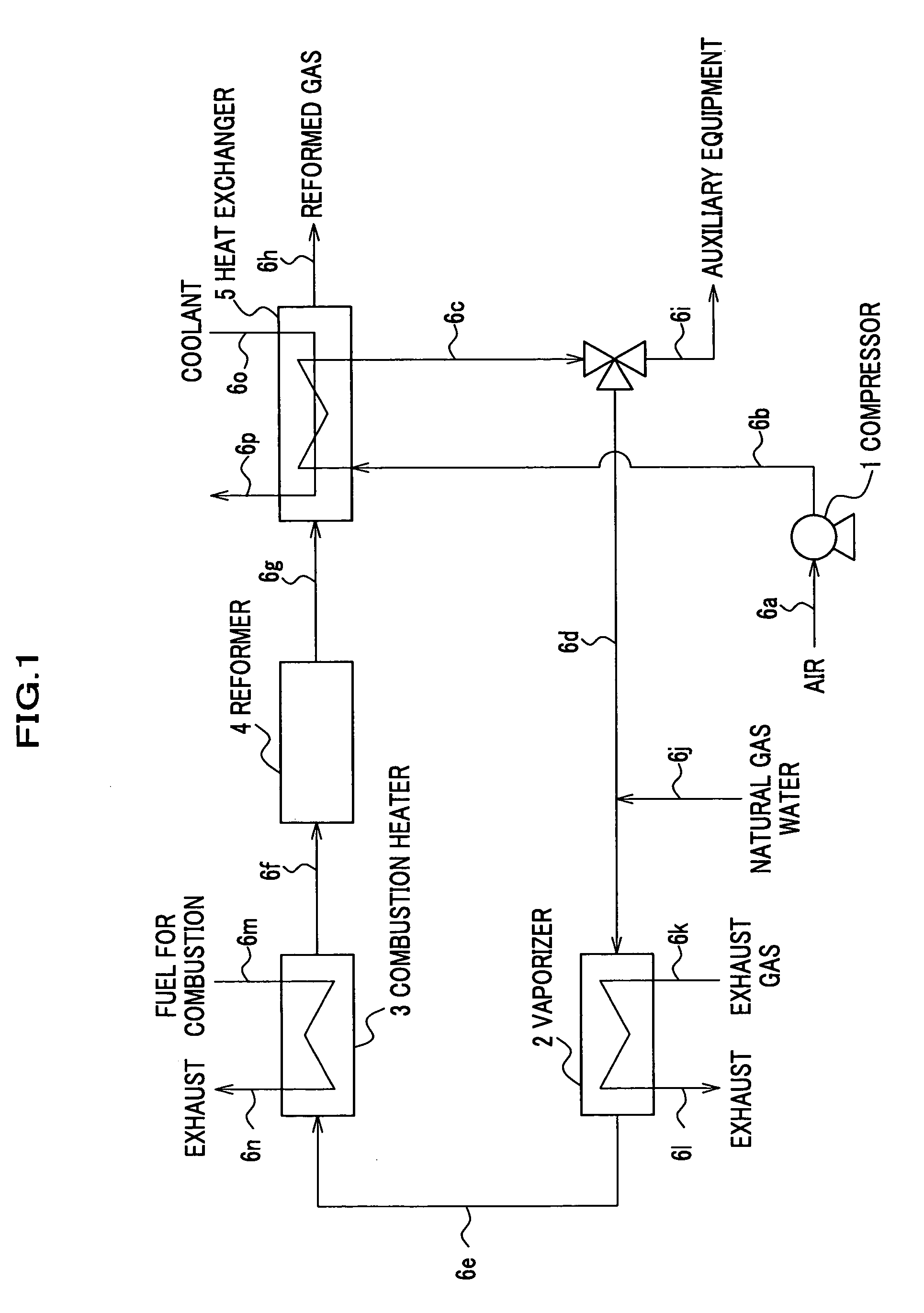
[0032] Hereinafter described is a first fuel reforming system that is configured to cool compressed air and a reformed gas using a coolant. The first fuel reforming system as shown in FIG. 1 includes a compressor 1, a vaporizer 2, a combustion heater 3, a reformer 4, a heat exchanger 5, and piping (pipes 6a-6p) installed to couple these units together. The compressor 1 generates compressed air to be supplied to the reformer 4 and other auxiliary equipment of various kinds. The vaporizer 2 heats a natural gas and water supplied from a feedstock supply system (not shown), together with the compressed air supplied from the compressor 1, to generate a steam fuel mixture. The combustion heater 3 burns a combustible fuel (e.g., a natural gas) and utilize...

second embodiment

[0057] A description will be given of a heat exchanger according to a second embodiment of the present invention with reference to FIG. 11. The heat exchanger 5 according to the second embodiment is, as shown in FIG. 11, substantially the same in structure as that according to the first embodiment, except that the body tube 10 serving to make up a shell of the heat exchanger 5 in the first embodiment is not provided; therefore, a duplicate description of the structure of the heat exchanger 5 is omitted herein.

[0058] The heat exchanger 5 according to the second embodiment lends itself, for example, to particular applications such that a high-temperature gas (first fluid) passing through first-fluid passages 41 is cooled using a coolant (second fluid) passing through second-fluid passages 51, and the coolant passing through the second-fluid passages 51 is cooled using air (third fluid) flowing around the second heat exchanger tubes 50. To be more specific, the heat exchanger 5 accord...

third embodiment

[0059] A description will be given of a heat exchanger according to a third embodiment of the present invention with reference to FIG. 12. The heat exchanger 5 according to the third embodiment is, as shown in FIG. 12, substantially the same in structure as that according to the second embodiment, except that a plurality of cooling fins 15 are provided in the third-fluid passage 13. The fins 15 may be attached to the outer walls of the second heat exchanger tubes 50 and exposed to the third-fluid passage 13. The heat exchanger 5 according to the third embodiment may be suitable for such particular applications as mentioned above in describing the second embodiment.


PUM

PropertyMeasurementUnit
temperatureaaaaaaaaaa

Abstract

End rings are coupled with upper and lower ends of a cylindrical body tube. A plurality of first heat exchanger tubes are fitted and held in holes provided in a pair of first tube plates. A plurality of second heat exchanger tubes are fitted and held in holes provided in a pair of second tube plates. The inside of each first heat exchanger tubes forms a first-fluid passage for carrying a reformed gas. The space defined between an outer wall of each first heat exchanger tube and an inner wall of the corresponding second heat exchanger tube forms a second-fluid passage for carrying a coolant. The space defined among an inner wall of the body tube and outer walls of the second heat exchanger tubes form a third-fluid passage for carrying compressed air.

Description

BACKGROUND OF THE INVENTION [0001] Apparatuses consistent with the present invention relate to heat exchangers capable of heat exchange among three or more fluids. [0002] The heat exchanger is a device for transferring heat energy from a high-temperature fluid to a low-temperature fluid, and is typically employed as a heating, cooling, or heat recovery device of various kinds in a chemical treatment system. For example, hydrogen for use in a fuel cell may generally be produced by subjecting hydrocarbon fuels (feedstocks) such as natural gases to reforming and other treatments, and a fuel reforming system for such a reforming treatment requires several types of heat exchangers. The heat exchangers for use with the fuel reforming system may include, for example: an air cooler for cooling high-temperature and high-pressure air used for reforming treatment and discharged from a compressor to render it reusable as air for driving auxiliary equipment; a gas cooler for cooling a high-tempe...

Claims


Application Information

Patent Timeline
Patent Type & Authority Applications(United States)
IPC IPC(8): F28F9/02C01B3/38F28D7/00F28D7/10F28D7/16F28F13/18
CPCC01B2203/0894C01B2203/1294F28D1/0461F28F2240/00F28D7/0083F28D7/106F28D7/1607F28D7/0066
Inventor ARAI, TAKASHIMACHIDA, JUNYOSHIDA, NOBUYOSHIMIZOJIRI, NORIYUKI
Owner HONDA MOTOR CO LTD
Why Eureka
Try Eureka