Optical viewing system and method for operating the same

a viewing system and optical technology, applied in the field of optical viewing systems, can solve the problems of chromatic aberration and low luminescent density of such displays, and achieve the effect of good signal-to-noise ratio

Active Publication Date: 2005-10-27
CARL ZEISS MEDITEC AG
View PDF9 Cites 39 Cited by
  • Summary
  • Abstract
  • Description
  • Claims
  • Application Information

AI Technical Summary

Benefits of technology

[0032] In another embodiment of the invention, a control unit can be provided which is assigned to a light source for illuminating light. A brightness signal of a video image, which is generated with the image sensor, is supplied to this control unit in order to so control the brightness

Problems solved by technology

What is problematic is the comparatively low luminescent density of such displays for the use in a surgical microscope.
This problem is also present in displays wherein the colored brightness impression of a pixel is caused by the intensity of the light emitted by a pixel insofar the display is operated in a video mode, in that a display pixel makes available seque

Method used


Image

  • Optical viewing system and method for operating the same
  • Optical viewing system and method for operating the same
  • Optical viewing system and method for operating the same

Examples


embodiment 400

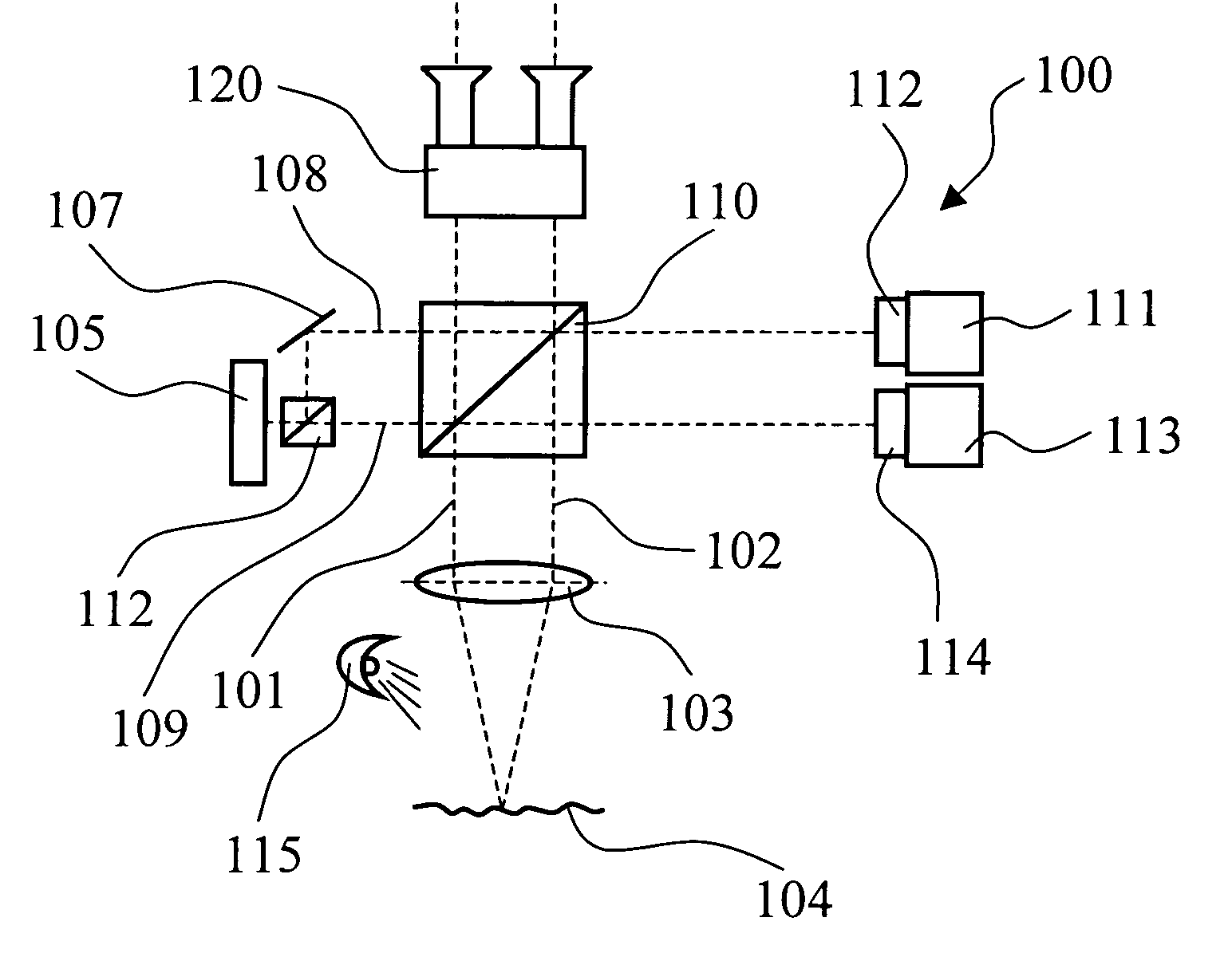
[0060]FIG. 4 shows a modified embodiment 400 for a surgical microscope as an optical viewing system with a unit for reflecting in data. With a stereoscopic viewing beam path (401, 402) through a surgical microscope main objective 403, the surgical microscope 400 makes possible the viewing of an object region 404 with a binocular tube 407. A rapidly switching display 405 is provided as a unit for reflecting in data and can be a DMD display or an FLC display. Basically, a slow switching display can also be used as display 405, for example, a nematic LCOS display.

[0061] The image of the display is superposed via a beam splitter cube 406 onto the image of the object region 404 and is supplied to a camera unit 408 having image sensor 409. A light source 410 is provided for illuminating the object region 404.

[0062] A neutral density filter 411 is mounted ahead of the image sensor 409. This neutral density filter 411 controls the light intensity of the image information impinging upon the...

embodiment 600

[0065]FIG. 6 shows a further modified embodiment 600 for a surgical microscope having a unit for reflecting in data. Assembly groups, which correspond to components of the viewing system explained with respect to FIG. 4, are provided with reference numerals increased by 200.

[0066] In the surgical microscope 600, a nematic LCOS display is provided as display 605. Compared to the DMD display or FLC display, this display can be switched only comparatively slowly. However, a quasi-continuous tuning of the intensity of the light, which is emitted from a pixel, is made possible.

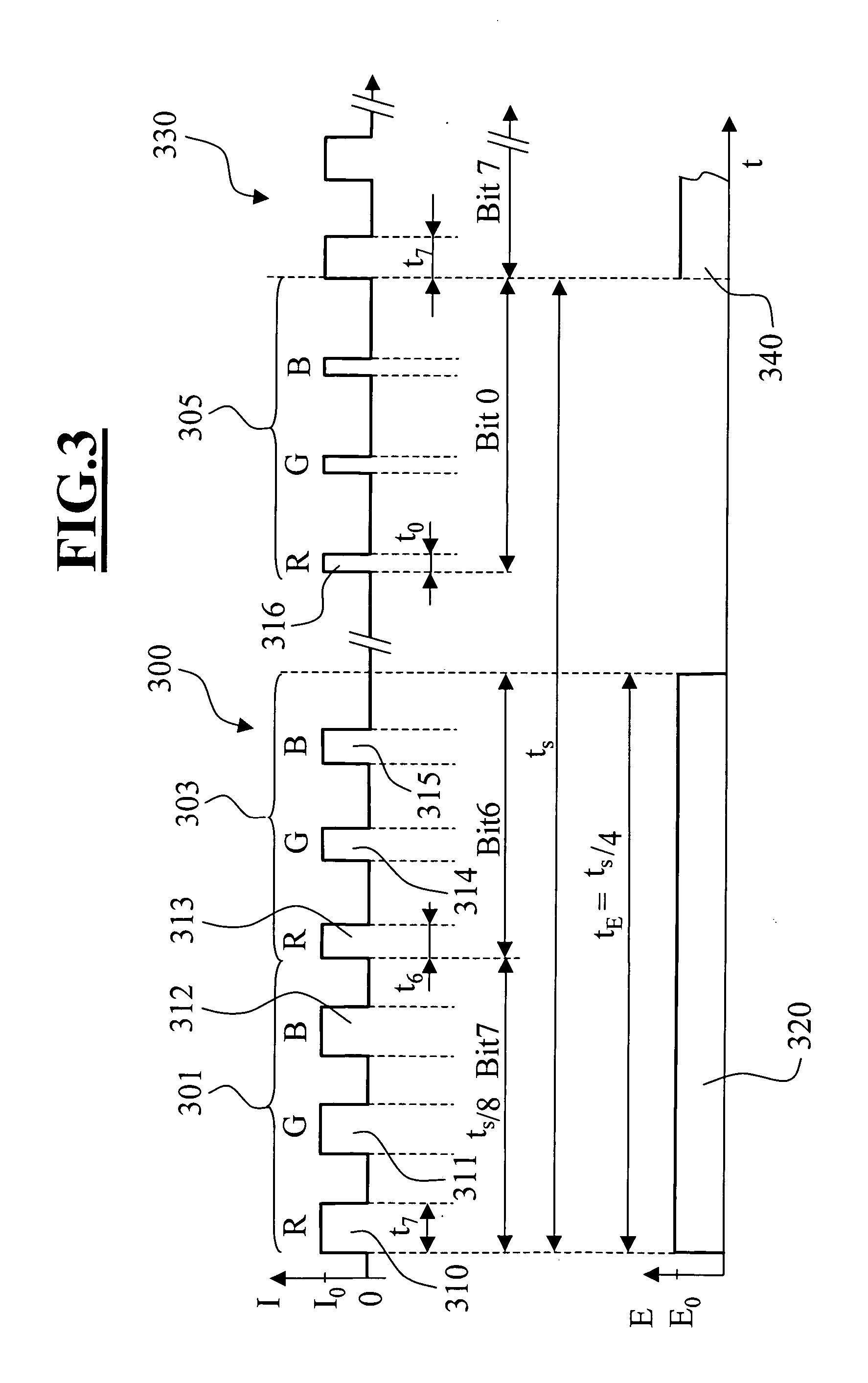
[0067] In FIG. 7, the intensity of the light, which is emitted from a display pixel, is plotted as a function of time. For an observer, in an image duration interval tS1 of approximately 20 ms, a pixel color impression having a color pulse train 730 is generated with the color pulse train 730 comprising three color pulses 701, 702 and 703. The colors of the color pulses are preferably in the complementary colors r...

embodiment 900

[0074]FIG. 9 shows a further modified embodiment 900 for a surgical microscope having a unit for reflecting in data. Component assemblies, which correspond to components of the viewing system explained with respect to FIG. 6, are provided with reference numerals increased by 300.

[0075] The surgical microscope 900 includes a 1-chip monochromatic CMOS image sensor 909. Such a monochromatic image sensor 909 is sensitive for light of the visible spectral range. The light from display 905 and the light from the object region 904 is superposed onto the image sensor 909 via a beam splitter 906. A CIE color filter wheel 911 is assigned to the illuminating unit 910 of the surgical microscope 900. The filter wheel contains three CIE color filters which are moved via a rapid rotation of the wheel 911 through the illuminating beam path of the surgical microscope 900. The movement of the CIE color filter wheel 911 is coupled to the image sensor 909 which is explained in detail with respect to FI...


PUM


Abstract

An optical viewing system (100) for viewing an object region has a display unit (105) which has a plurality of controllable display segments which make available color pulse sequences in order to generate a display image which is built up of a plurality of image points. The optical viewing system (100) includes a superposition unit (110) which superposes an image, which is made available by the display unit (105), onto the image of an object region (104). The optical viewing system has a camera unit (111, 113) to which the superposed image of display unit (105) and object region (104) is supplied. The camera unit (111, 113) has image sensors (112, 114) whose light sensitivity is adjustable as a function of time. The light sensitivity of the image sensors (112, 114) is matched to the color pulse sequence in such a manner that the image sensor (112, 114) can detect at least two light pulses of different color from the color pulse sequence from a display segment.

Description

CROSS REFERENCE TO RELATED APPLICATIONS [0001] This application claims priority of German patent applications no. 103 37 795.6, filed Aug. 14, 2003, and no. 10 2004 038 001.5, filed Aug. 4, 2004, the entire contents of which are incorporated herein by reference. FIELD OF THE INVENTION [0002] The invention relates to an optical viewing system for viewing an object region. The viewing system includes a display unit which has a plurality of controllable display segments which make available light in different colors in order to generate a colored display image which is built up of a plurality of image points. The viewing system further includes a superposition unit which superposes an image, which is made available by the display unit, onto the image of an object region. The viewing system further includes a camera unit which is supplied with an image of display unit and object region superposed by the superposition unit. The camera unit has an image sensor whose light sensitivity is a...

Claims


Application Information

Patent Timeline
IPC IPC(8): G02B7/00G02B21/00G02B21/22G02B21/36H04N13/239
CPCG02B21/0012G02B21/22G02B21/361H04N13/0429G02B26/008G02B26/023H04N13/0239G02B21/365H04N13/332H04N13/239
Inventor JESS, HELGEGOLD, ULRICHQUENDT, DIETERHAUGER, CHRISTOPH
Owner CARL ZEISS MEDITEC AG
Why Eureka
Try Eureka