Method and system for self-convergent erase in charge trapping memory cells

a technology of charge trapping memory cells and self-convergent erase, which is applied in the direction of digital storage, instruments, semiconductor devices, etc., can solve the problems of cell over-erase, and achieve the effects of reducing negative charge, negative charge, and over-erase condition

Active Publication Date: 2005-10-27
MACRONIX INT CO LTD
View PDF56 Cites 121 Cited by
  • Summary
  • Abstract
  • Description
  • Claims
  • Application Information

AI Technical Summary

Benefits of technology

[0009] In general, a method for operating a charge trapping memory cell is provided. The memory cell has a first channel terminal acting as a drain or source, a second channel terminal acting as a source or drain, a charge trapping structure and a gate terminal. The method for operating the memory cell includes establishing a high threshold state in the memory cell by injecting negative charge into the charge trapping structure to set a threshold voltage for the cell above a high state threshold. The method includes using a self-converging biasing procedure to establish a low threshold state for the memory cell by reducing the negative charge in the charge trapping structure to set the threshold voltage for the cell below a specified value for the low threshold state. The negative charge is reduced in the memory cell by applying a bias procedure including at least one bias pulse. The bias pulse induces injection of holes into the charge trapping layer and / or induces the ejection of electrons from the charge trapping layer, at a rate responsive to the amount of negative charge in the charge trapping structure during a bias pulse, and induces injection of electrons into (and / or holes out of) the charge trapping structure during the bias pulse when the amount of negative charge in the charge trapping structure is reduced sufficiently that the threshold voltage is near or below the low threshold state. In this manner, self-convergence occurs during the bias pulse by which the threshold voltage of the memory cell converges on a desired value, and an over-erase condition is avoided.

Problems solved by technology

Under the biasing arrangement of the first bias pulse, some cells may suffer over-erase due to excess holes in the charge trapping structure.

Method used


Image

  • Method and system for self-convergent erase in charge trapping memory cells
  • Method and system for self-convergent erase in charge trapping memory cells
  • Method and system for self-convergent erase in charge trapping memory cells

Examples


Embodiment Construction

[0027] A detailed description of embodiments of the present invention is provided with reference to FIGS. 1-11.

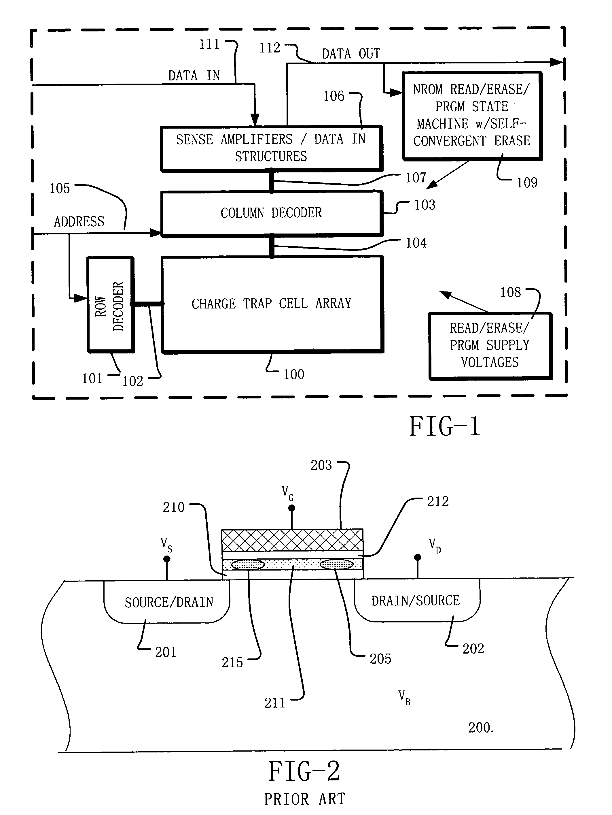
[0028]FIG. 1 is a simplified block diagram of an integrated circuit supporting self-convergent erase according to the present invention. The integrated circuit includes a memory array 100 implemented using NROM memory cells, or other charge trapping memory cells. A page / row decoder 101 is coupled to a plurality of word lines 102 arranged along rows in the memory array 100. A column decoder 103 is coupled to a plurality of bit lines 104 arranged along columns in the memory array 100. Addresses are supplied on bus 105 to column decoder 103 and page / row decoder 101. Sense amplifiers and data-in structures in block 106 are coupled to the column decoder 103 via data bus 107. Data is supplied via the data-in line 111 from input / output ports on the integrated circuit to the data-in structures in block 106. Data is supplied via the data-out line 112 from the sense amplifiers in bl...


PUM


Abstract

A process and a memory architecture for operating a charge trapping memory cell is provided. The method for operating the memory cell includes establishing a high threshold state in the memory cell by injecting negative charge into the charge trapping structure to set a high state threshold. The method includes using a self-converging biasing procedure to establish a low threshold state for the memory cell by reducing the negative charge in the charge trapping structure to set the threshold voltage for the cell to a low threshold state. The negative charge is reduced in the memory cell by applying a bias procedure including at least one bias pulse. The bias pulse balances charge flow into and out of the charge trapping layer to achieve self-convergence on a desired threshold level. Thereby, an over-erase condition is avoided.

Description

RELATED APPLICATIONS [0001] The present application claims priority to U.S. Provisional Application No. 60 / 565,377 filed 26 Apr. 2004. The present application also claims priority to U.S. Provisional Application No. 60 / 566,669 filed 30 Apr. 2004.BACKGROUND OF THE INVENTION [0002] 1. Field of the Invention [0003] The present invention relates to operating methods for electrically programmable and erasable non-volatile memory and integrated circuits including such memory, and more particularly to methods for establishing low threshold states, and for correction and prevention of over-erase conditions in such devices. [0004] 2. Description of Related Art [0005] Electrically programmable and erasable non-volatile memory technologies based on charge storage structures known as EEPROM and flash memory are used in a variety of modern applications. A number of memory cell structures are used for EEPROM and flash memory. As the dimensions of integrated circuits shrink, greater interest is ar...

Claims


Application Information

Patent Timeline
Patent Type & Authority Applications(United States)
IPC IPC(8): G11C16/04H01L29/788H01L29/792
CPCG11C16/0466H01L29/792H01L29/7885
Inventor ZOUS, NIAN-KAITSAI, WEN-JERCHEN, HUNG-YUEHLU, TAO-CHENG
Owner MACRONIX INT CO LTD
Why Eureka
Try Eureka