Method and an apparatus for measuring phase noise
a technology of phase noise and measurement apparatus, which is applied in the direction of pulse characteristics measurement, transmission monitoring, instruments, etc., can solve the problems of limiting the accuracy of phase noise measurement, the inability to realize the necessary phase noise properties of conventional apparatuses for measuring phase noise, and the limitation of the improvement of the performance of the apparatus for measuring phase noise. , to achieve the effect of reducing the spurious effect of this signal source, reducing the number of times processing is performed per unit of time, and reducing the spurious
- Summary
- Abstract
- Description
- Claims
- Application Information
AI Technical Summary
Benefits of technology
Problems solved by technology
Method used
Image
Examples
first embodiment
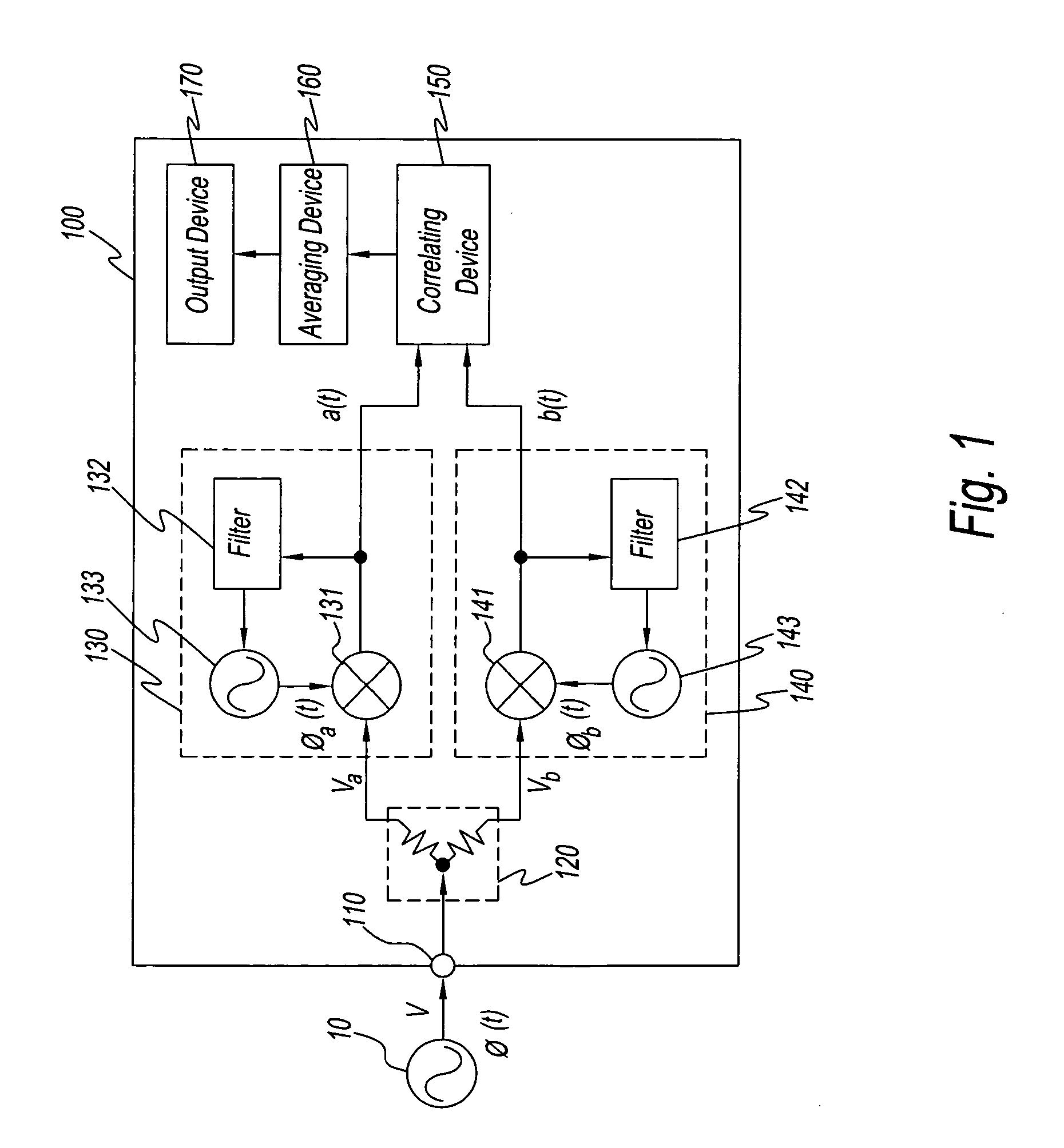
[0031] Preferred embodiments of the present invention will now be described while referring to the attached drawings as needed. the present invention is an apparatus 100 for measuring phase noise. A block diagram showing the structure of apparatus 100 for measuring phase noise is shown in FIG. 1. A device under test 10 and apparatus 100 for measuring phase noise are shown in FIG. 1.
[0032] Device under test 10 outputs signals V under test, which are the object of phase noise measurement. Device under test 10 is a signal source or a part, apparatus, or system that applies signals.
[0033] Phase noise measurement apparatus 100 is constructed as described below. That is, phase noise measurement apparatus 100 consists of an input terminal 110, a distributor 120, a PLL block 130, which is an example of a phase detection means, a PLL block 140, which is an example of a phase detection means, a correlating device 150; an averaging device 160, and an output device 170. Input terminal 110 is a...
seventh embodiment
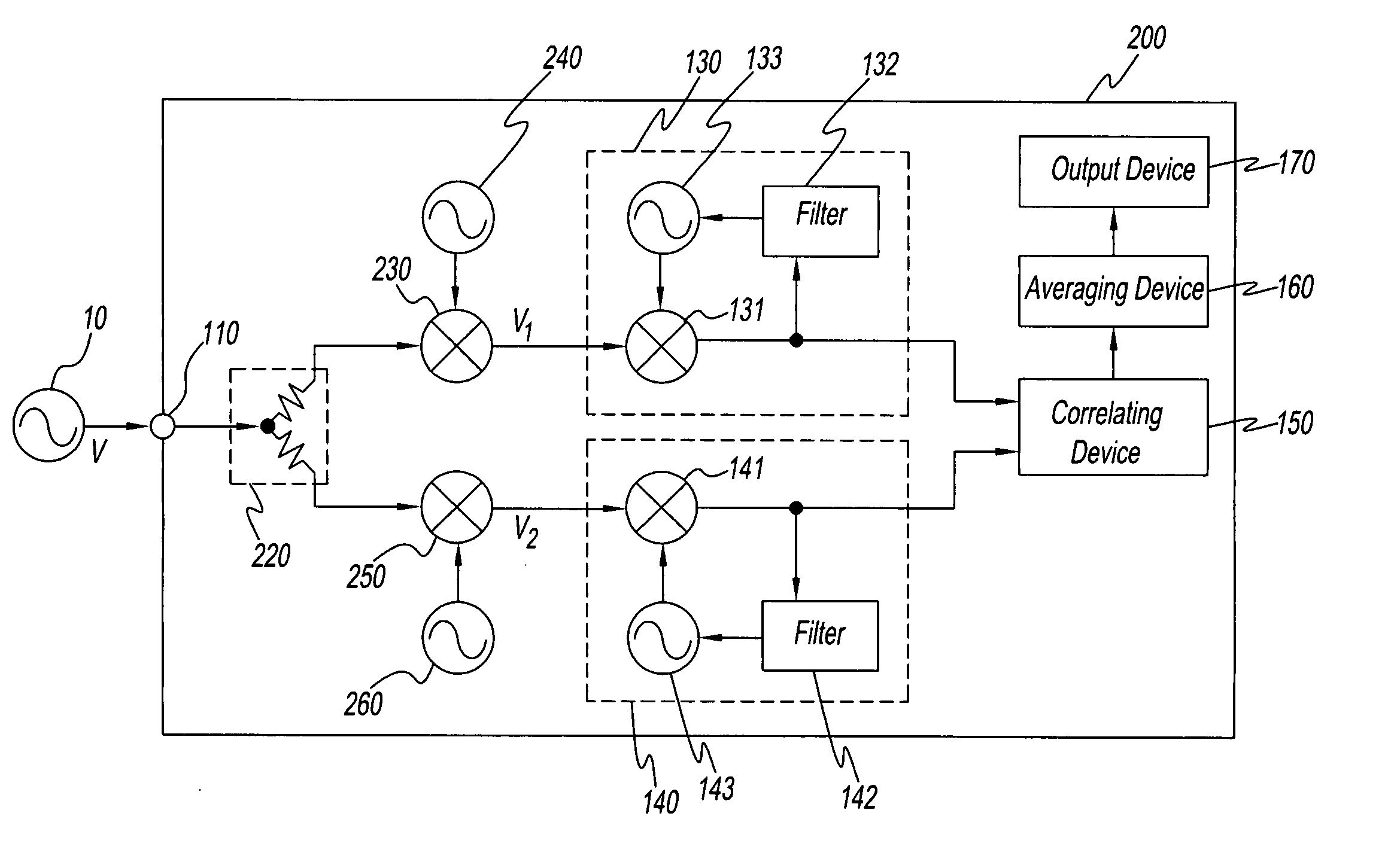
[0093] A block diagram showing the structure of the present invention, an apparatus 700 for measuring phase noise, is shown in FIG. 9. The same reference symbols are used in FIG. 9 for the same structural elements as in FIG. 1 and a description thereof is omitted. Apparatus 700 for measuring phase noise in FIG. 9 is apparatus 100 for measuring phase noise wherein a PLL block 710 is substituted for PLL block 130 and a PLL block 730 is substituted for PLL block 140. PLL block 710 is PLL block 130 in which a signal source 720 is substituted for signal source 133. PLL block 730 is PLL block 140 in which a signal source 740 has been substituted for signal source 143.
[0094] Signal source 720 has a reference signal source 721 and a synthesizer 722. Synthesizer 722 generates and outputs local signals while referring to the output signals of reference signal source 721. The frequency and phase of the output signals of synthesizer 722 are controlled by the output signals of filter 132. Moreov...
eighth embodiment
[0131] By means of the eighth embodiment, the cross spectrum of two phase signals is found for a plurality of frequency ranges having different frequency bands. That is, correlating blocks 920, 930, and 940 having different frequency bands essentially are assigned a frequency band and find the cross spectrum. As a result, it is not necessary for each correlating block to have excess operating functions. For instance, the total amount of memory inside each correlating block is much smaller than the amount of memory needed when a frequency band is not assigned. Moreover, when a plurality of cross spectra are obtained within the predetermined same time, correlating blocks 920, 930, and 940 perform vector averaging in terms of time on the respective resulting plurality of cross spectra. As a result, measurement resources are conserved and precision efficiency is improved in that noise flow is reduced.
[0132] The following modifications can be applied to each of the embodiments described ...
PUM
 Abstract
Description
Claims
Application Information
 - R&D
- Intellectual Property
- Life Sciences
- Materials
- Tech Scout
- Unparalleled Data Quality
- Higher Quality Content
- 60% Fewer Hallucinations
Browse by: Latest US Patents, China's latest patents, Technical Efficacy Thesaurus, Application Domain, Technology Topic, Popular Technical Reports.
© 2025 PatSnap. All rights reserved.Legal|Privacy policy|Modern Slavery Act Transparency Statement|Sitemap|About US| Contact US: help@patsnap.com


