Dispersion compensation quantity setting method, receiving terminal station, and wavelength-multiplexing optical transmission system

a technology of optical transmission system and quantity setting method, which is applied in the direction of electromagnetic transmission, multi-communication, wavelength-division multiplex system, etc., can solve the problems of difficulty in long-distance transmission, waveform distortion, and limitation, so as to improve transmission quality and reliability, reduce examination efforts, and promote the effect of reducing parts cos

Inactive Publication Date: 2005-10-27
FUJITSU LTD
View PDF6 Cites 27 Cited by
  • Summary
  • Abstract
  • Description
  • Claims
  • Application Information

AI Technical Summary

Benefits of technology

[0026] The present invention has been developed in consideration of these problems, and it is therefore an object of the invention to provide a dispersion compensation quantity setting method, receiving terminal station and wavelength-multiplexing optical transmission system, capable of compensating effectively for dispersion quantity, improving the transmission quality and reliability, separately evaluating waveform distortions stemming from the self phase modulation SPM and a cross phase modulation XPM, coupled with promoting the reduction of parts cost and reducing the efforts for examination on the number of wavelengths, distance and others needed for maintaining the transmission capability or performance.
[0028] Therefore, this can set the reception dispersion compensation quantity so as to reduce the influence of the cross phase modulation XPM and, hence, the effective dispersion quantity compensation becomes feasible in a manner such that a variable dispersion compensator is provided in the reception terminal station.
[0034] This can suppress the waveform distortion, thus easing the NF (Noise Figure) of an optical amplifier or the characteristic of a transmitter / receiver in design, which leads to relaxing the restrictions in specification on devices and parts constituting the optical amplifier and the transmitter / receiver, thereby promoting the parts cost reduction. Moreover, a manager can maintain the transmission capability or performance without taking into consideration the decrease in number of wavelengths of wavelength-multiplexed light, the shortening of distance, or the like.

Problems solved by technology

Accordingly, on the other side of the expansion of the transmission capacity, waveform distortions occurs and difficulty is experienced in making long-distance transmissions.
On the other hand, on the enlargement of wavelength band, limitation is imposed due to the amplification characteristics of devices themselves, such as an EDFA (Erbium-Doped Optical Fiber Amplifier).
That is, since limitation is imposed on the device amplified wavelength bandwidth, difficulty is encountered in enlarging the wavelength band.
On the other hand, in a case in which an optical fiber transmission line is on land, in view of cost, difficulty is experienced in making the interval between the repeating nodes constant, and the dispersion compensation quantity needed for each repeating span (repeating zone) is not always made constant.
Furthermore, various methods of individually carrying out the effective compensation on the self phase modulation SPM and the effective compensation on the cross phase compensation XPM have been known, whereas a method of carrying out both these compensations simultaneously is difficult in design.
In addition to this, the realization of the optimization becomes difficult for taking into consideration the differences among the performances of the optical fibers, optical amplifiers and others and, hence, for example, a manager decreases the number of wavelengths or shortens the transmission distance, which can lead to the degradation of the performances.
Meanwhile, the aforesaid Japanese Patent 1 can compensate for the XPM introduced into a first span after a transmitter but it cannot compensate for the XPM occurring due to the nonlinear optical effects in the second and subsequent spans as a result of the light intensity amplified in a relevant amplifier.
In addition, difficulty is encountered in setting the dispersion compensation quantity variably.
Therefore, it does not provide a mode taking both the self phase modulation SPM and cross phase modulation XPM into consideration.

Method used


Image

  • Dispersion compensation quantity setting method, receiving terminal station, and wavelength-multiplexing optical transmission system
  • Dispersion compensation quantity setting method, receiving terminal station, and wavelength-multiplexing optical transmission system
  • Dispersion compensation quantity setting method, receiving terminal station, and wavelength-multiplexing optical transmission system

Examples


first embodiment

(A) Description of First Embodiment of the Present Invention

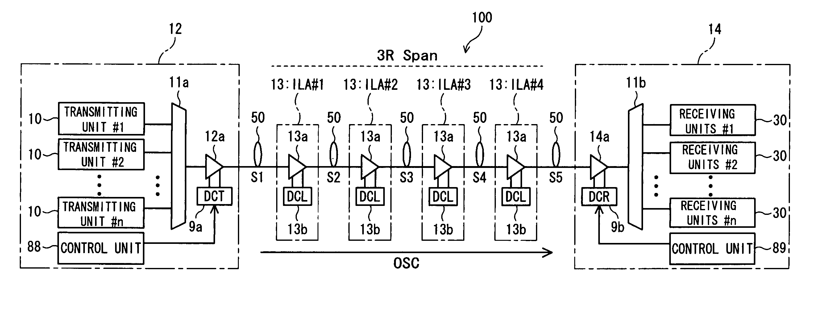
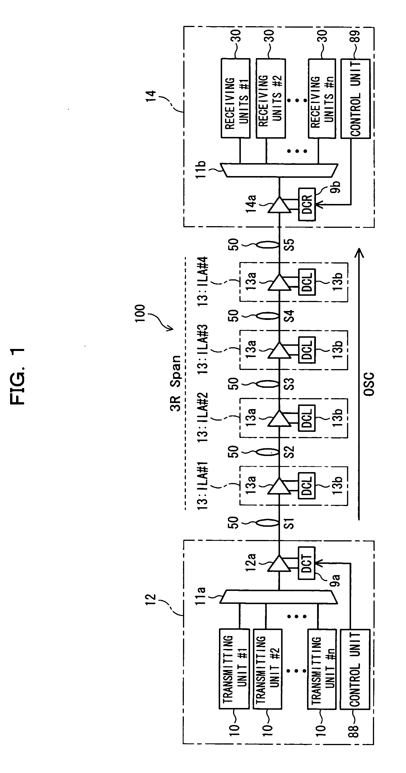
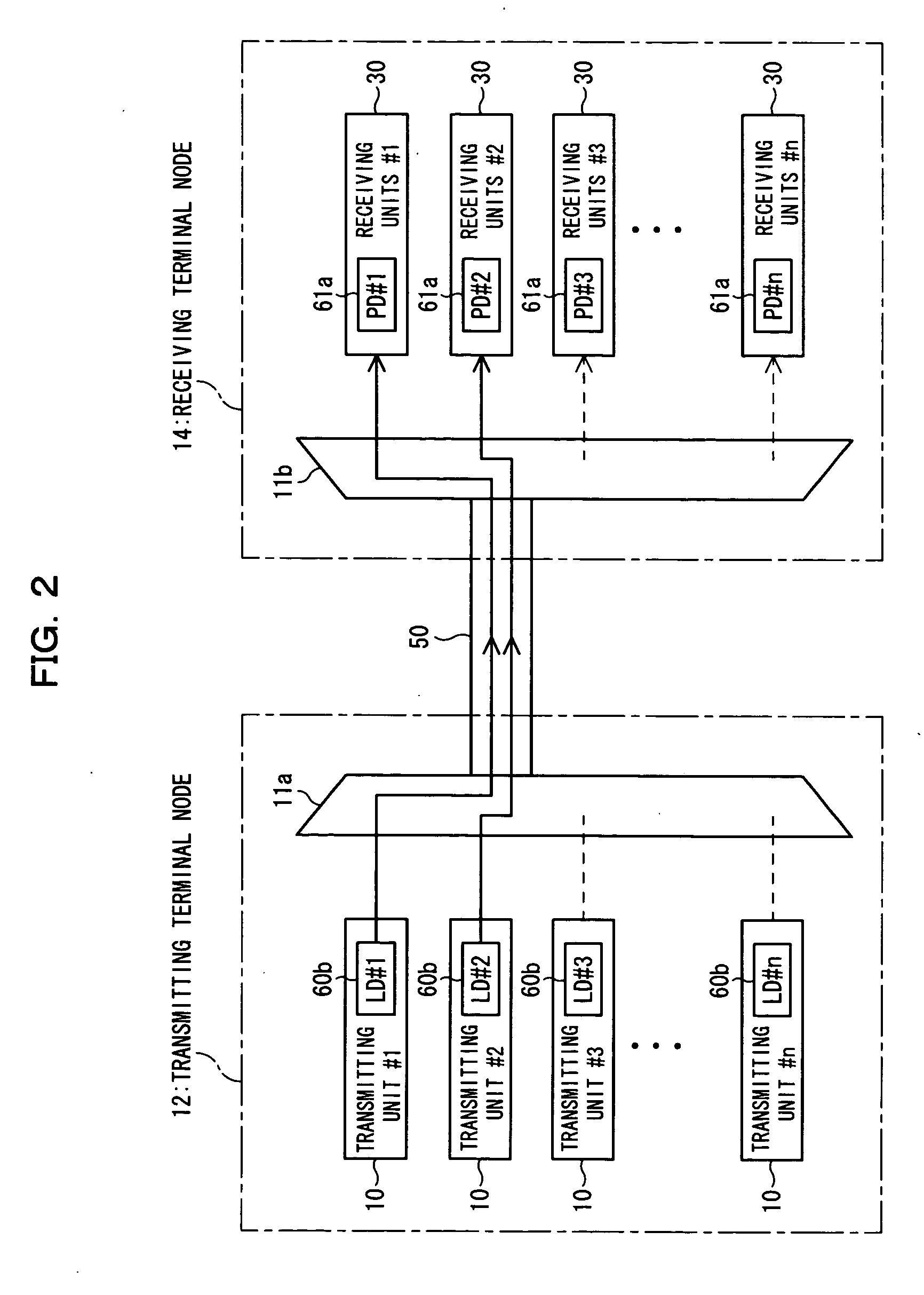
[0065]FIG. 1 is a schematic illustration of a configuration of a WDM transmission system according to a first embodiment of the present invention. The WDM transmission system shown in FIG. 1 is made up of a transmitting terminal node (transmitting terminal station, transmitting node or a transmitting terminal station unit) 12 and a receiving terminal node (receiving terminal station, receiving node or a receiving terminal station unit) 14 for transmitting wavelength-multiplexed light (wavelength-multiplexed signal light) obtained by multiplexing wavelengths different from each other inn channels (n represents a natural number)

[0066] (1) WDM Transmission System 100

[0067] (1-1) Outline of Configuration of WDM Transmission System

[0068] One example of the WDM transmission system 100 according to the present invention serves as a trunk network system. For example, nodes located in broad areas such as Tokyo, Hawaii and Los Ang...

second embodiment

(B) Description of Second Embodiment of the Present Invention

[0290] Each node (transmitting terminal node 12, receiving terminal node 14 and repeating node 13) can transmit wavelength-multiplexed light bidirectionally and can compensate for the dispersion bidirectionally. In the second embodiment, each of the transmitting terminal node 12 and the receiving terminal nod 14 is equipped with a reception dispersion compensator (DCR) and a transmission dispersion compensator (DCT).

[0291]FIG. 20 is a schematic illustration of a configuration of a WDM transmission system according to the second embodiment of the present invention. The WDM transmission system 100b shown in FIG. 20 is designed to transmit wavelength-multiplexed light bidirectionally, and it is made up of a transmitting / receiving terminal node (transmitting / receiving terminal station) 22, a transmitting / receiving terminal node (transmitting / receiving terminal station) 24 and, for example, four repeating nodes 13, and optical...


PUM


Abstract

In a dispersion compensation quantity setting technique for use in a WDM transmission system, a transmitting terminal node transmits CW light and modulated light obtained by modulation using a modulation pattern signal, while a receiving terminal node detects a physical quantity stemming from cross phase modulation occurring between the transmitting terminal node and the receiving terminal node on the basis of a variation of an intensity of the transmitted CW light and sets a dispersion compensation quantity on the basis of a variation of the detected physical quantity. Moreover, this optimizes the crosstalk, suppresses the output power of transmitted light, eliminates the nonlinear optical effect of the transmitted light, and carries out dispersion compensation superior in cost performance.

Description

BACKGROUND OF THE INVENTION [0001] (1) Field of the Invention [0002] The present invention relates to, for example, in a WDM (Wavelength Division Multiplexing) linear repeating transmission system (which will hereinafter be referred to as a WDM transmission system), a dispersion compensation quantity (value) setting method, receiving terminal station and wavelength-multiplexing optical transmission system, suitable for the compensation for waveform distortions occurring due to nonlinear optical effects and the compensation for chromatic dispersions. [0003] (2) Description of the Related Art [0004] In general, for the transmission of wavelength-multiplexed light, a WDM transmission system (WDM optical communication system) using an optical amplifier is effective in the reduction of circuit cost. In this WDM transmission system, the enhancement of bit rate and the improvement of wavelength density are indispensable to the expansion of transmission capacity. [0005] (i) Expansion of Tra...

Claims


Application Information

Patent Timeline
Patent Type & Authority Applications(United States)
IPC IPC(8): H04B10/07H04B10/2507H04B10/2519H04B10/2525H04B10/255H04B10/2557H04J14/00H04J14/02
CPCH04B10/25133H04B10/0795
Inventor SEKIYA, MOTOYOSHIMIYASHITA, TAKUYA
Owner FUJITSU LTD
Why Eureka
Try Eureka