
Electric driven protein immobilizing module and method

a technology of immobilizing module and protein, which is applied in the direction of peptides, liquid/fluent solid measurement, inorganic carrier, etc., can solve the problems of weak adsorption binding force drawback, protein peeling from the support, and inability to re-use the support, so as to shorten the protein/enzyme diffusion time, accelerate the adsorption of protein/enzyme, and reduce the effect of enzymatic activity

Inactive Publication Date: 2005-10-27
IND TECH RES INST
View PDF2 Cites 1 Cited by
  • Summary
  • Abstract
  • Description
  • Claims
  • Application Information

AI Technical Summary

Benefits of technology

[0012] The primary objective of this specific invention is to provide a protein immobilizing module driven by an electric field. According to the invention, in a solution environment, an electric field may be used to control the orientation of protein / enzyme and accelerate the adsorption of the protein / enzyme to a selected support. This can resolve the problem of diminishing enzymatic activity which caused by masking the active site of the protein / enzyme, and also shortening the protein / enzyme diffusion time.

Problems solved by technology

However it has a drawback of weak adsorption binding force.
The protein is prone to peel off from the support due to external factors such as changes of temperature, pH value, and ionic concentration in the solution.
However, the support cannot be regenerated and reused.
However, the protein loses its enzymatic activity easily.
All of the techniques for immobilizing protein set forth above have two main common problems.
To some supports (such as filter paper or semi-permeable membrane), the incubation approach could lead to planar (lateral) diffusion on the support and result in non-uniform (uneven) distribution of the protein / enzyme on the support.
Moreover, such approach could result in leakage of the protein / enzyme through the pores of the support under forceful suction.
The disadvantage of said conventional methods for protein immobilization is the lengthy time for the protein / enzyme to bind to the support.

Method used


Image

  • Electric driven protein immobilizing module and method
  • Electric driven protein immobilizing module and method
  • Electric driven protein immobilizing module and method

Examples


Embodiment Construction

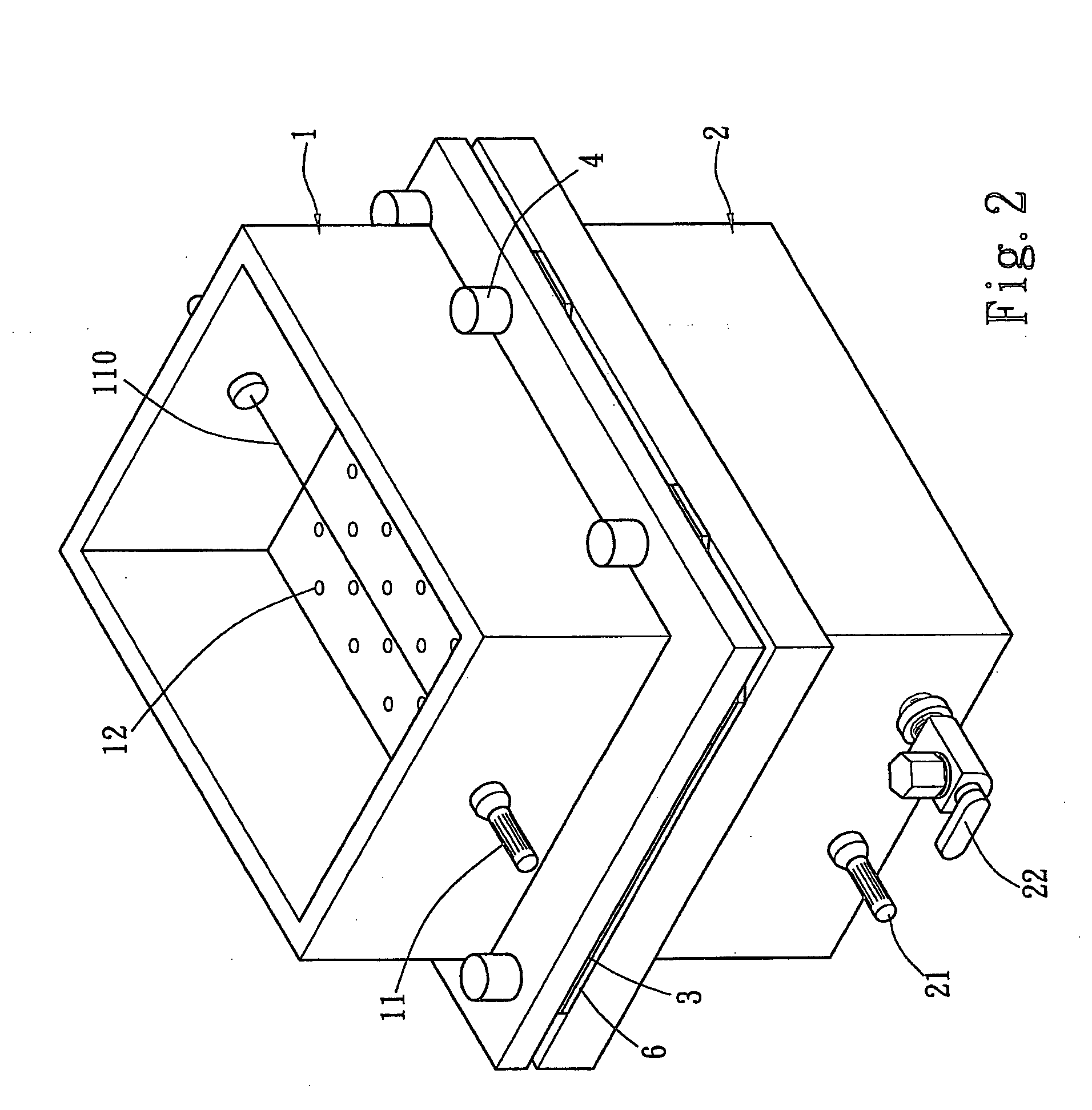
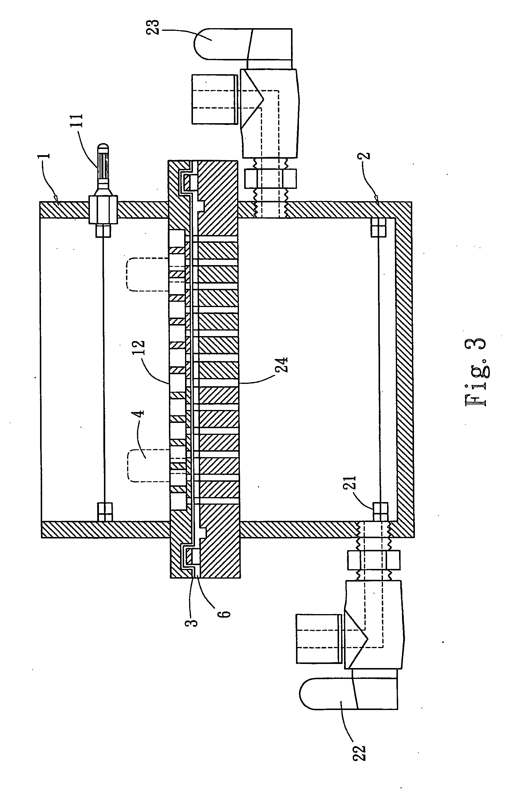
[0021] Please refer to FIG. 2 for the structure of the module according to the invention. It includes an upper tank 1 and a lower tank 2. The upper tank 1 can open on the upper side and the lower side. The lower tank 2 is closed and has only one end communicating with the upper tank 1. The upper tank 1 has a first electrode 11 which is a cathode. The first electrode 11 is connected to a platinum wire 110 which is mainly to generate an electric field. The platinum wire 110 may also be replaced by a conductive metal plate. The lower tank 2 has a second electrode 21 which is an anode. The two modules are interposed by a silicon rubber pad 6 to prevent leaking. A selected support 3 is located on the surface of the silicon rubber pad 6 and is a porous membrane, porous powders or porous granules. In the embodiment, the support 3 is a porous membrane which may be made from cellulose nitrate, nylon, Polyvinylidene fluoride (PVDF), cellulose, or combinations thereof. The porous powders may c...


PUM

PropertyMeasurementUnit
voltageaaaaaaaaaa
pHaaaaaaaaaa
temperatureaaaaaaaaaa

Abstract

An electric driven protein immobilizing module and method aims at immobilizing proteins rapidly and steadily on the surface of a selected support. The invention employs the characteristics of proteins / enzymes forming a slightly negative charge in a buffer solution. An external electric field is set up to drive the proteins / enzymes to be adsorbed onto the support. The invention improves upon conventional absorption or bonding methods that fix the protein in a non-directional approach which results in masking the protein active site and subsequently loss the protein activity. Thus activity of the protein / enzyme improved, while the time-consuming problem and enzymatic activity loss problem of incubation and vacuum absorption method may be avoided.

Description

FIELD OF THE INVENTION [0001] The present invention relates to a protein immobilizing module and method, and particularly to an apparatus and method that employ an external electric field to move the protein / enzyme and shorten the diffusion time. BACKGROUND OF THE INVENTION [0002] Proteins are mainly composed of amino and carboxylic acid functional group. Hence immobilizing the protein generally is accomplished by forming a bond between the amino (—NH2) and carboxylic (—COOH) group on a support. In general, the methods for immobilizing proteins can be divided into three types. [0003] The first type is carrier-binding which immobilizes the protein on an insoluble support (i.e. solid type). Carrier-binding methods further can be grouped in three categories: [0004] a. Physical adsorption: which adsorbs the protein through physical characteristics such as van der waals interaction or hydrogen bonding. It has the advantages of low cost and also the bond can be formed easily. However it h...

Claims


Application Information

Patent Timeline
Patent Type & Authority Applications(United States)
IPC IPC(8): C12N11/06C12N11/14
CPCC12N11/14
Inventor OHARA, REIKOYUAN, CHIUN-JYEHO, WEI-JEN
Owner IND TECH RES INST
Learn More