
Methods for treating mitral valve annulus with biodegradable compression element

a compression element and mitral valve technology, applied in the field of ablation catheter or probe system, can solve the problems of end-organ failure, severe lifestyle restrictions, death of patients, etc., and achieve the effects of reducing and/or shrinking, enhancing tissue shrinkage, and high frequency energy

Inactive Publication Date: 2005-10-27
QUANTUM COR
View PDF8 Cites 141 Cited by
  • Summary
  • Abstract
  • Description
  • Claims
  • Application Information

AI Technical Summary

Benefits of technology

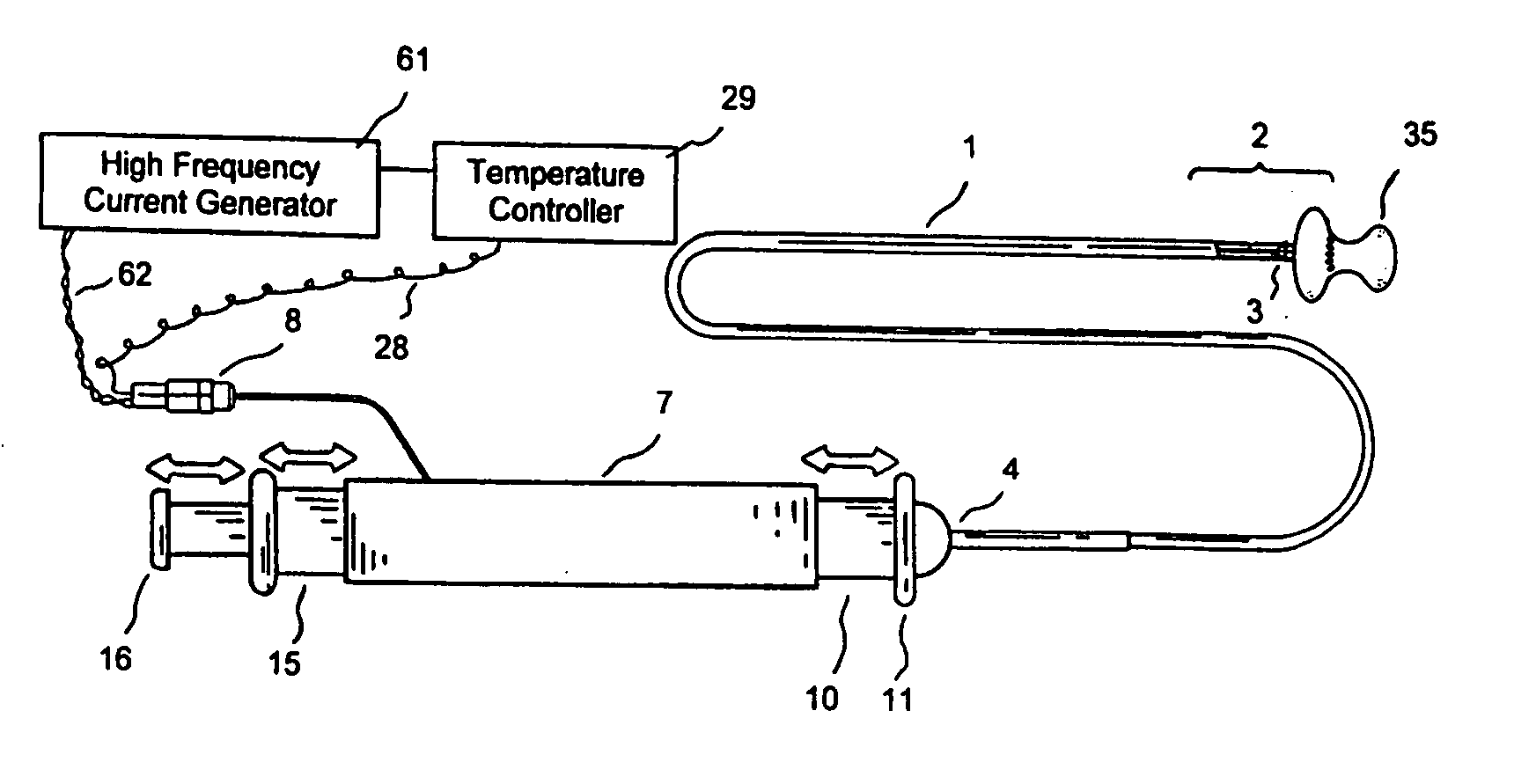
[0032] It is still another object of the present invention to provide a catheter system and methods for providing high frequency current to a restriction device, possibly biodegradable, designed to be transversely advanced and deployed within the cardiac vein via the coronary sinus and in some embodiments other coronary veins. This device, when heated, will place tension on adjacent structures, reducing the diameter and / or limiting the expansion of the mitral annulus and / or diastolic expansion of the left ventricle.
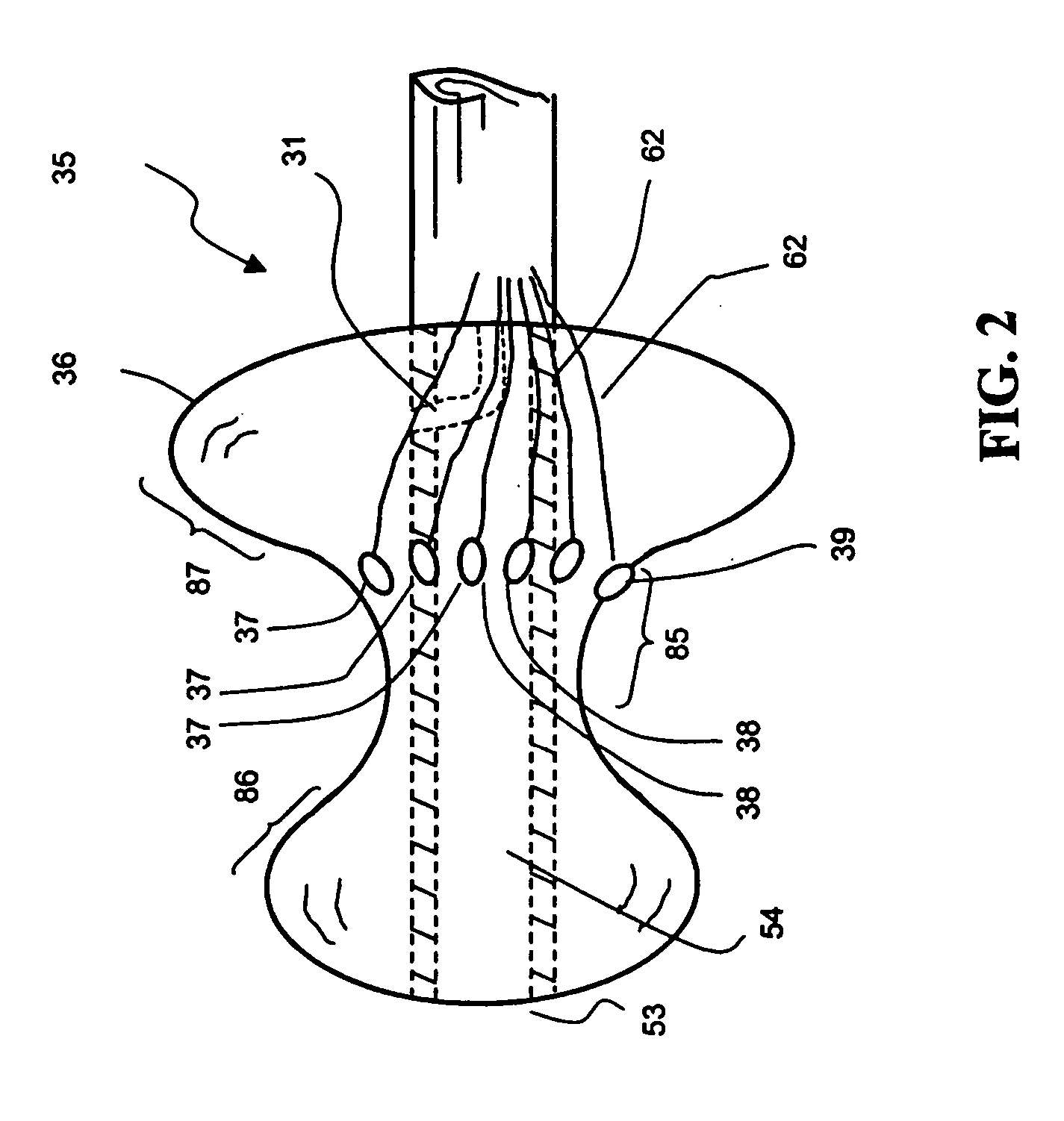
[0035] In any of the above-stated objects, the system of the invention further comprises a temporary tissue-compressing element, such as an open ring-like structure, to maintain the target organ structure in a shrunk state for a desired period of duration. In one embodiment, the temporary tissue-compressing element is made of biodegradable material that is sized and configured to maintain its compression capability in a sufficient duration (before it loses its compression capability due to biodegradation) effective to enhance the tissue shrinkage by using high frequency energy. In another embodiment, the biodegradable compression element is inserted into coronary sinus effective to tighten at least a portion of the mitral annulus. In still another embodiment, the biodegradable compression element is placed across the annulus to pull the opposite sides of the annulus a short distance approaching each other effective to tighten at least a portion of the mitral annulus. The catheter system of the present invention has several significant advantages over known catheters or ablation techniques for repairing an annular organ structure of a heart valve, a valve leaflet, chordae tendinae, papillary muscles, venous valve, sphincter, and the like. In particular, the ablation catheter of this invention by using high frequency current energy for reducing and / or shrinking a tissue mass may tighten and stabilize the dilated tissue at or adjacent a valvular annulus, plus benefits from the temporary tissue compression element to maintain the shrunk tissue at its shrunk state until the shrunk tissue is stabilized.

Problems solved by technology

CHF can ultimately lead to end-organ failure, which contributes to death of the patient.
If untreated, CHF may result in severe lifestyle restrictions and ultimately death.
One of the causes of CHF and a very common contributor to the harmful effects of CHF is a leaky mitral heart valve.
Valve replacement using a tissue valve suffers long-term calcification problems.
The current technology for valve repair or valve replacement requires an expensive open-heart surgery that needs a prolonged period of recovery.
A less invasive or catheter-based valve repair technology becomes an unmet clinical challenge.
Many of the defects are associated with dilation of the valve annulus.
This dilatation not only prevents competence of the valve but also results in distortion of the normal shape of the valve orifice or valve leaflets.
All of the above valve repair or replacement requires an open-heart operation which is costly and exposes a patient to higher risk and longer recovery than a catheter-based, less invasive procedure.
This method applies appropriate heat to the tissues, and causes them to shrink and tighten.
However, the assembly disclosed by Edwards et al. does not teach a tissue-contactor member comprising a narrow middle region between an enlarged distal region and an enlarged proximal region suitable for sandwiching and compressing the sphincter for tissue treatment.
However, it is not disclosed for focused ultrasound energy for repairing a mitral valve or an atrioventricular valve annulus.

Method used


Image

  • Methods for treating mitral valve annulus with biodegradable compression element
  • Methods for treating mitral valve annulus with biodegradable compression element
  • Methods for treating mitral valve annulus with biodegradable compression element

Examples


Embodiment Construction

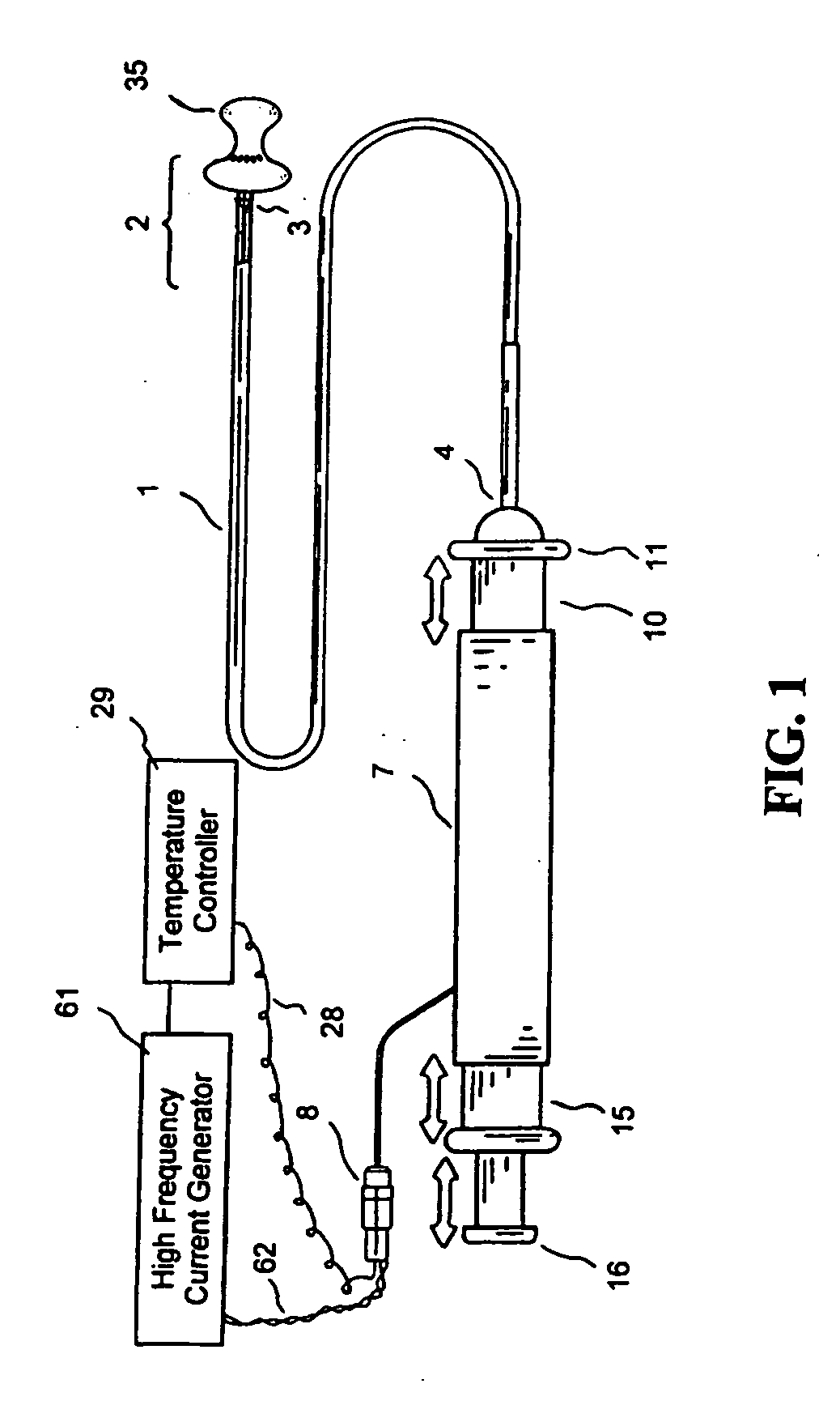
[0058] The following descriptions of the preferred embodiment of the invention are exemplary, rather than limiting, and many variations and modifications are within the scope of the invention. What is shown in FIGS. 1 to 21 is an embodiment of the present invention to provide a treating system that selectively contacts the tissue of an annulus in order to tighten and stabilize an annular organ structure adapted for repairing an annular organ structure defect of a patient. The system may be deployed via a catheter percutaneously or via a cannula through a percutaneous intercostal penetration or applied directly to the annular organ via open surgical access. The annular organ structure or the annulus to be treated may be selected from the group consisting of a mitral valve, a tricuspid valve, a pulmonary valve, an aortic valve, a venous valve, and a sphincter.

[0059]“Sandwich” as a verb is herein meant to place an object between usually two things of another quality or character; part...


PUM


Abstract

A catheter system and methods for repairing a valvular annulus or an annular organ structure of a patient comprising intimately contacting the annular organ structure by a tissue-contactor member having energy-delivering elements, and delivering tissue-shrinkable energy at the annular organ structure through the elements, wherein the tissue-shrinkable energy is applied at a distance wirelessly from the elements sufficient to shrink and tighten the organ structure.

Description

[0001] This application takes priority from U.S. Provisional Application Ser. No. 60 / 515,221 filed Oct. 28, 2003 the specification of which is hereby incorporated herein by reference.FIELD OF THE INVENTION [0002] The present invention generally relates to a system and methods for applying therapeutic energy to a patient for medical purposes such as reducing and / or shrinking a tissue mass. More particularly, the invention relates to an ablation catheter or probe system that selectively contacts the tissue of a valvular annulus in order to tighten and stabilize an annular organ structure and is adapted for repairing an annular organ structure defect in a patient, utilizing either a percutaneous, minimally invasive, or surgical approach. BACKGROUND OF THE INVENTION [0003] Over 12 million people around the world suffer from Congestive Heart Failure (CHF). This is a family of related conditions defined by the failure of the heart to pump blood efficiently resulting in congestion (or back...

Claims


Application Information

Patent Timeline
Patent Type & Authority Applications(United States)
IPC IPC(8): A61B17/00A61B18/14A61F7/00A61F7/12
CPCA61B18/1492A61B2017/00004A61B2018/00214A61B2018/00267A61B2018/00261A61B2018/00291A61B2018/00369A61B2018/0022
Inventor TU, HOSHENGWITZEL, THOMASHAUCK, WALLACE
Owner QUANTUM COR
Learn More