Hoisting device with vertical motion compensation function

a hoisting device and function technology, applied in the direction of passenger handling apparatus, hoisting equipment, servomotor, etc., can solve the problems of large energy consumption, inability to perform accurate and speedy observations or works, increase costs, etc., and achieve high degree of accuracy, save consumption energy of hoisting device, and improve response.

Inactive Publication Date: 2005-11-03
MITSUI ENG & SHIPBUILD CO LTD +2
View PDF5 Cites 59 Cited by
  • Summary
  • Abstract
  • Description
  • Claims
  • Application Information

AI Technical Summary

Benefits of technology

[0019] The present invention thus constructed, the wire is payed out or rolled up by controlling the discharge amount of the operating oil of the hydraulic pump to eliminate the effects of the vertical motion of the wire hanging point. Therefore, a crane boom or the like as a large-sized heavy object is not required to be moved vertically, as a result, the whole hoisting device can be small-sized. In addition, the consumption energy of the hoisting device can be saved. Furthermore, since the wire is payed out or rolled up without moving the large-sized structure in the present invention, the wire can be payed out or rolled up, following the vertical motion of the hanging point of the wire easi

Problems solved by technology

In such cases, when a hull is moved vertically by waves, an equipment such as the observation instrument in the water is also moved vertically in accordance with the vertical motion of the hull, as a result, accurate and speedy observations or works can not be performed.
However, the above crane system 2 has the following problems.
Since the crane boom 4 composing the aforementioned crane system 2 is a large-sized heavy object, a l

Method used


Image

  • Hoisting device with vertical motion compensation function
  • Hoisting device with vertical motion compensation function
  • Hoisting device with vertical motion compensation function

Examples


Embodiment Construction

[0025] Some embodiments of a hoisting device with a vertical motion compensation function according to the present invention will be described in detail with reference to the accompanying drawings.

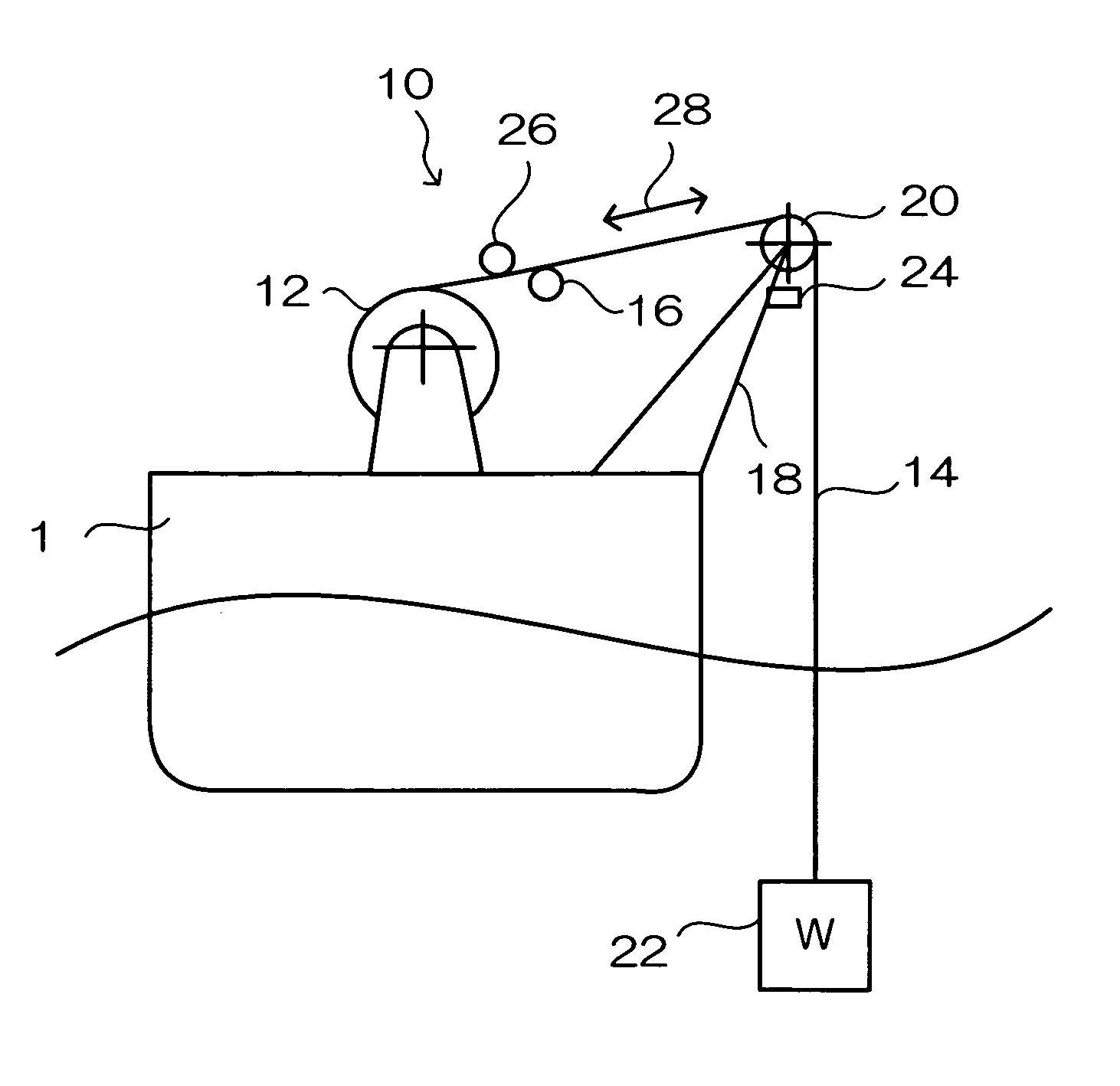
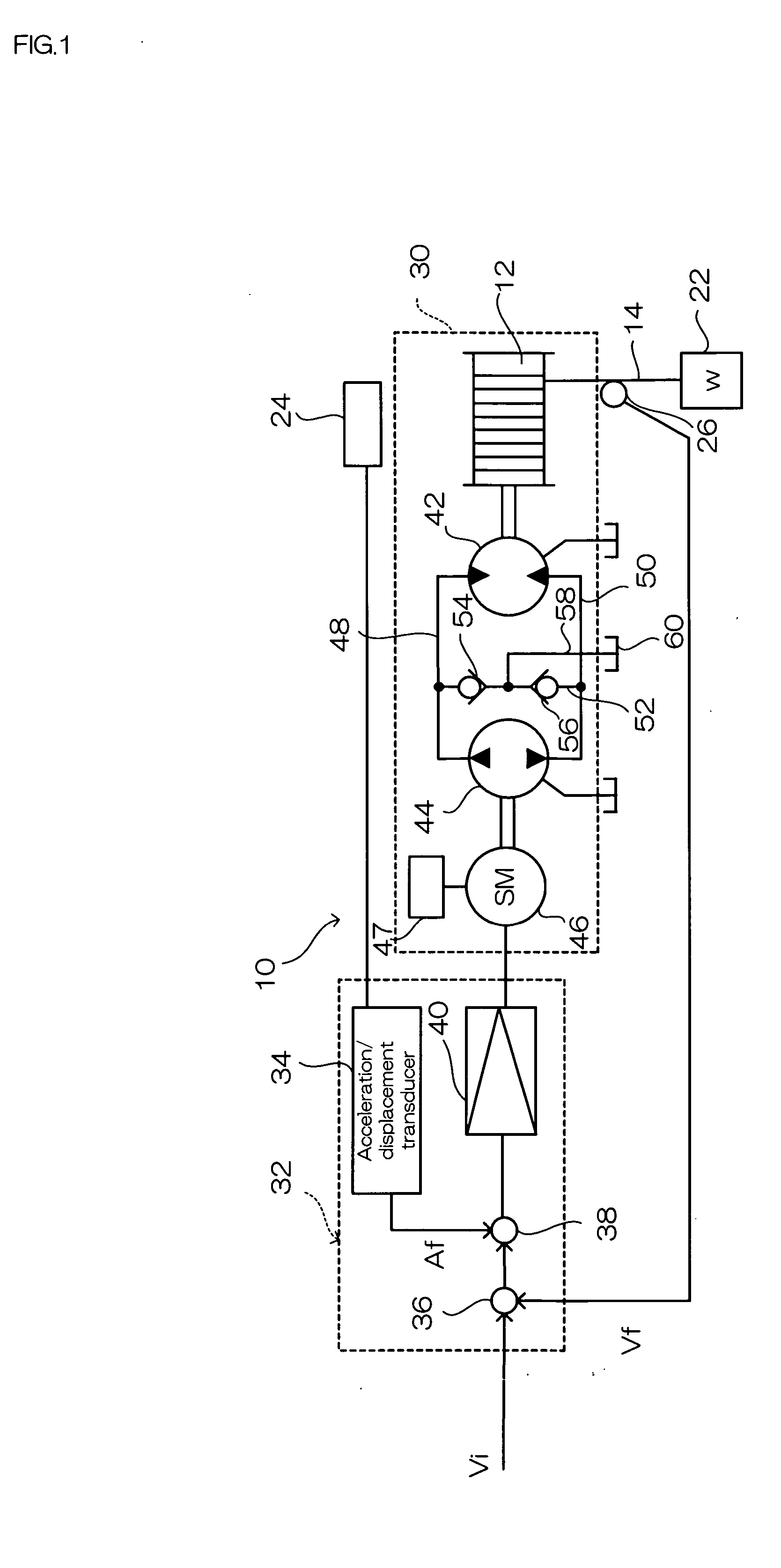
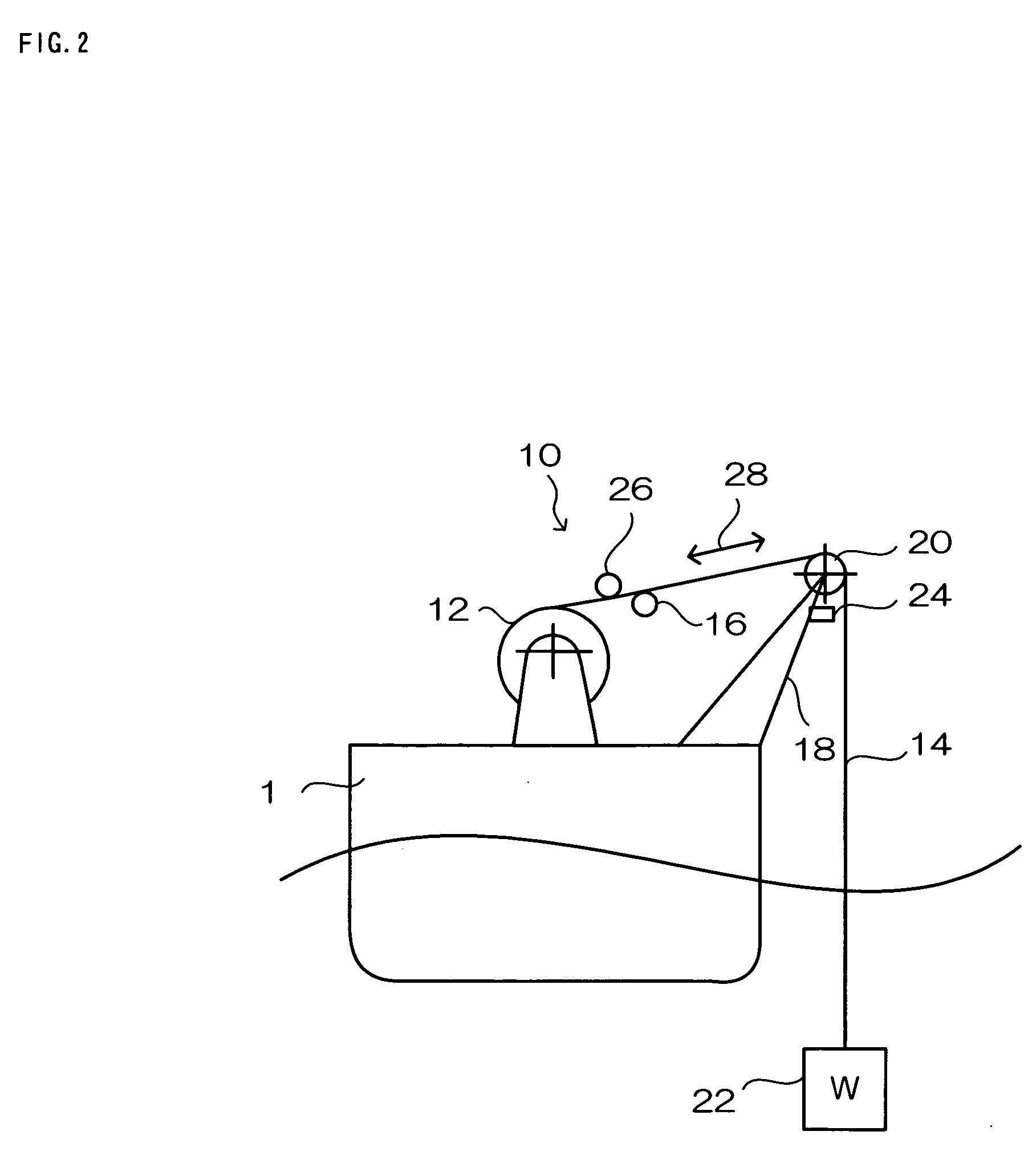
[0026]FIG. 1 and FIG. 2 are explanatory drawings of a hoisting device with a vertical motion compensation function according to a first embodiment the present invention. In FIG. 2, a hoisting device 10 has a drum 12 disposed on a deck of a hull 1, constituting the hoisting device. The drum 12 can freely rotates, and can roll up or pay out a wire 14 wound thereon. A tip of the wire 14 hangs from a pulley 20, guided by the pulley 20 installed at a tip of a boom 18 through a guide roller 16 so as to be freely rotatable. And an equipment 22 such as a CTD measuring instrument is hung at the tip of the wire 14. An acceleration sensor 24 as being a vertical motion sensor is provided at the same position as the pulley 20, which is to be a hanging point of the wire 14. The acceleration sensor dete...


PUM


Abstract

A hoisting device can be small-sized and energy can be saved. A hoisting device 10 according to the present invention has a hoist 30 and a control unit 32. The hoist 30 rotates a drum 12 having a wire 14 wound thereon by an oil pressure motor 42 rotatable in normal and reverse directions. To the oil pressure motor 42, operating oil is supplied from an oil pressure pump 44. The oil pressure pump 44 is a two-way discharge fixed capacity type, and rotated by a servomotor 46. An acceleration/displacement transducer 34 in the control unit 32 finds a moving direction and a moving speed of a wire hanging point in the vertical direction from an output signal of an acceleration sensor 24. The control unit 32 outputs a drive control signal of the servomotor 46 according to a paying-out speed or a rolling-up speed of the wire 14 offsetting the vertical motion of the wire hanging point caused by the heaving of a hull based on a speed instruction Vi of the paying-out or rolling-up speed of the wire, a detected signal of the acceleration sensor 24 and a detected signal of a wire speed sensor 26.

Description

BACKGROUND OF THE INVENTION [0001] 1. Field of the Invention [0002] This invention relates to a hoisting device with a vertical motion compensation function, especially the hoisting device with the vertical motion compensation function eliminating effects by the heaving of a ship caused by waves with respect to an article hung from the ship through a wire. [0003] 2. Description of the Related Art [0004] In the prevailing oceangraphic observation, the sea area is grasped three-dimensionally based on the data of a vertical distribution and a horizontal distribution of a salinity concentration, a water temperature and a water depth measured at the same time. There is a CTD (conductivity temperature depth) observation instrument as an instrument for gathering the above data. The observation instrument is used for observing the CTD under a situation maintained in a constant depth, hung by a winch from a board of a ship to the sea. There is a case that measurements are performed, allowing...

Claims


Application Information

Patent Timeline
IPC IPC(8): B63B27/08B63B27/36B66C23/52B66D1/00B66D1/52F15B11/00
CPCB66D1/52Y10S254/90
Inventor UEKI, SHUJIDOI, HIROHUMIMIYAJIMA, SHOGOHASEGAWA, KENZOSATOH, HIROSHI
Owner MITSUI ENG & SHIPBUILD CO LTD
Why Eureka
Try Eureka