Method and an apparatus for distance measurement

a distance measurement and apparatus technology, applied in the field of distance monitoring, can solve the problems of enormous amount of time and money, comparatively high measurement system cost, etc., and achieve the effect of reducing the threshold and increasing the sensitivity

Inactive Publication Date: 2005-11-10
IBEO AUTOMOBILE SENSOR
View PDF6 Cites 67 Cited by
  • Summary
  • Abstract
  • Description
  • Claims
  • Application Information

AI Technical Summary

Benefits of technology

[0022] A particular advantage of the invention consists of the fact that, in principle, any number of events, ultimately only limited by the resolution of the time pattern, can be measured in one single measurement, i.e. for one single transmitted radiation pulse. If a reflection of the transmitted radiation pulse takes place at a plurality of objects—whereby the received analog signal contains a corresponding number of signal pulses and, consequently, the received logic signal contains a corresponding number of logic pulses—the time pattern formed by the logic units of the logic circuit automatically contains the information on the distances of all objects. In accordance with the invention, a plurality of events can thus be measured for a single transmitted radiation pulse and so practically simultaneously.
[0023] The measurement method or measurement system hereby has so-to-say a “built-in” noise tolerance, since a noise pulse admittedly surpassing a threshold, but not corresponding to an object of interest would indeed be detected, but would not block the measurement device for all signal pulses arriving later. It is rather the case that occasional noise pulses would initially be measured like “normal” events. An evaluation unit downstream of the logic circuit can be designed such that noise pulses can be recognized as such in the later evaluation and can then be eliminated.
[0024] In an application of the invention, e.g. in laser scanners which are used, for example, in motor vehicles, a noise pulse would already be eliminated by algorithms for the recognition and tracking of objects during the evaluation e.g. in that no further reflections can be detected in the neighborhood of an “object” initially simulated by the noise pulse which are expected for objects actually present in the environment of the vehicle fitted with the laser scanner.
[0025] Furthermore, the noise tolerance in accordance with the invention advantageously permits the threshold of a threshold circuit to be placed closer to the noise than is possible with measurement systems which are already “blind” for following signals in the same measurement, i.e. with respect to the same transmitted radiation pulse, after one signal or a low number of signals exceeding the threshold.
[0026] In that, in accordance with the invention, the threshold can be lowered with respect to known measurement systems without impairing the evaluation of the distance data, a considerable increase in sensitivity can be achieved with the method or system in accordance with the invention.
[0027] Preferred embodiments of the invention are also recited in the dependent 1 claims, in the description and in the drawing.

Problems solved by technology

Particularly with laser measurement systems, an enormous amount of time and money is used to try to achieve a measuring precision or measuring resolution which is as high as possible, since very short time intervals have to be measured due to the speed of light.
To be able to satisfy demands of this kind on the time measurement, special ASIC modules have previously been used which makes the resulting measurement systems comparatively expensive due to the high development costs.

Method used


Image

  • Method and an apparatus for distance measurement
  • Method and an apparatus for distance measurement
  • Method and an apparatus for distance measurement

Examples


Embodiment Construction

[0046] The following description of the preferred embodiment(s) is merely exemplary in nature and is in no way intended to limit the invention, its application, or uses.

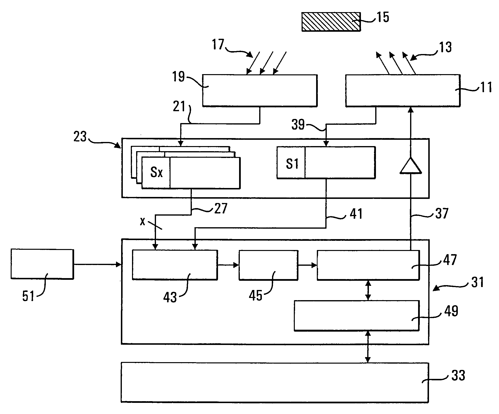
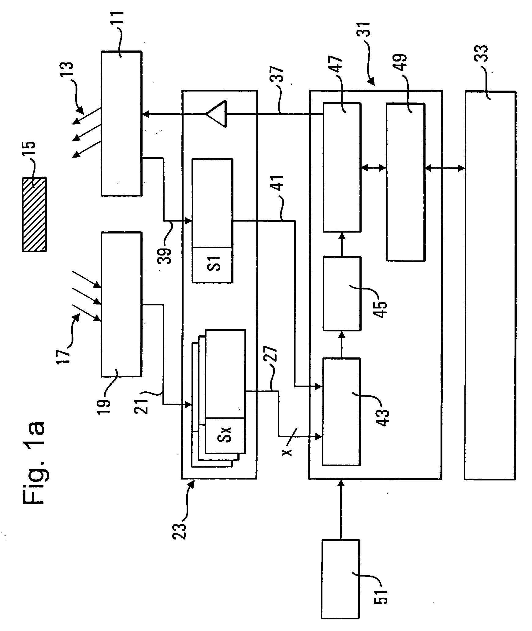
[0047]FIG. 1a shows a distance measurement system in accordance with the invention which is designed for one receiver channel. A multi-channel version is generally also possible in which the reflected signal pulses are simultaneously detected by means of a plurality of receivers and the received analog signals are processed in parallel in the manner in accordance with the invention.

[0048] A radiation pulse 13 transmitted as the result of a trigger signal 37 from a transmitter 11 including, for example, a laser diode is detected by a receiver 19 including, for example, a diode of the APD type after reflection at one or more objects 15 in the form of one or more reflected signal pulses 17. The receiver 19 generates the received analog signal 21 also termed a backscatter curve in the form of an electric voltage which ...


PUM


Abstract

The invention relates to a method for distance measurement by determining the pulse transit time, in which pulsed electromagnetic radiation is transmitted using at least one transmitter and signal pulses reflected at objects are detected using at least one receiver, wherein at least one received logic signal containing logic signals is generated from the received analog signal containing the signal pulses, in particular by means of a threshold circuit, and is evaluated with respect to the transit times of the logic signals, and wherein the received logic signal is read into a programmable logic circuit by means of a clocked data reading device and is mapped onto a time pattern in the logic circuit, in that instantaneous values of the received logic signal are stored in logic units of the logic circuit associated with the time windows for time windows of the time pattern corresponding to at least one clock pulse of the data reading device. The invention moreover relates to an apparatus for distance measurement.

Description

CROSS-REFERENCE TO RELATED APPLICATIONS [0001] This application claims the benefit of German Application No. 10 2004 022 912.0, filed May 10, 2004, and European Application No. EP 04 030 615.1, filed Dec. 23, 2004. The disclosures of the above applications are incorporated herein by reference. FIELD OF THE INVENTION [0002] The invention relates to a method for distance monitoring using transmitted and received radiation. BACKGROUND OF THE INVENTION [0003] The invention relates to a method for distance measurement by determination of the pulse transit time, in which pulsed electromagnetic radiation is transmitted using at least one transmitter and signal pulses reflected at objects are detected using at least one receiver, wherein at least one received logic signal containing logic signals is generated from the received analog signal containing the signal pulses, in particular by means of a threshold circuit, and is evaluated with respect to the transit times of the logic signals. [0...

Claims


Application Information

Patent Timeline
Patent Type & Authority Applications(United States)
IPC IPC(8): G01S7/32G01P3/36G01S1/30G01S7/487G01S13/08
CPCG01S7/4873
Inventor KIEHN, MICHAELGOSCH, KIRSTENKOHLER, MICHAELWILLHOEFT, VOLKER
Owner IBEO AUTOMOBILE SENSOR
Why Eureka
Try Eureka