
Method and a system for programming an industrial robot

a robot and industrial technology, applied in the field of industrial robot programming, can solve the problems of complex cad-system, time-consuming teaching process, trouble,

Active Publication Date: 2005-11-10
ABB (SCHWEIZ) AG
View PDF12 Cites 66 Cited by
  • Summary
  • Abstract
  • Description
  • Claims
  • Application Information

AI Technical Summary

Benefits of technology

[0009] The object of the present invention is to provide an improved industrial robot programming solution, which reduces the teaching time for the teaching process and increases the quality of the processing result in the first iteration.
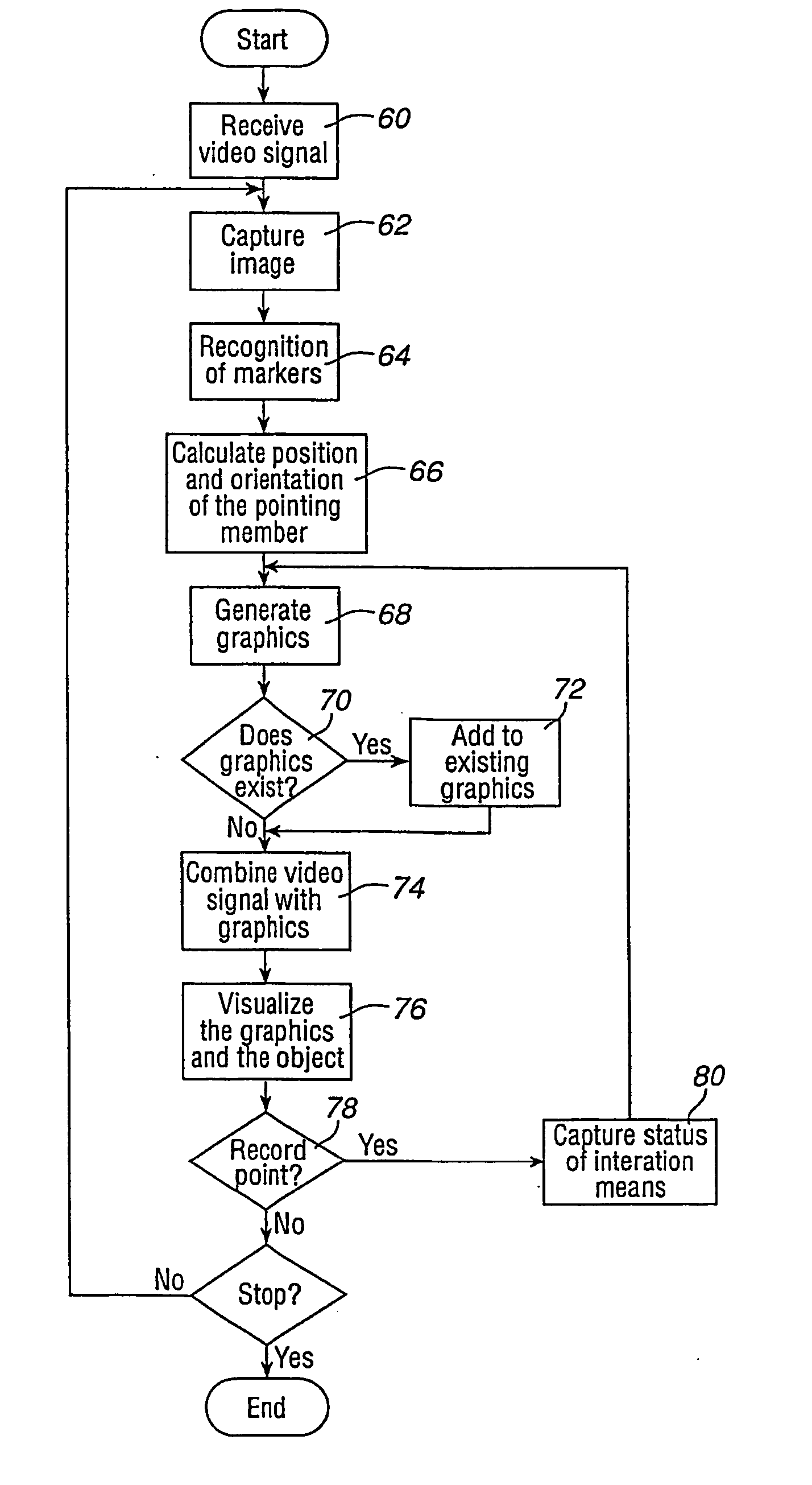
[0011] This method improves the teaching process by visualizing recorded information about the waypoints of the robot path in real time and in relation to the real object to be processed. Computer generated information, representing the robot path taught by the operator, is displayed or visualized projected on the object. Thus, the operator gets real-time visual feedback on his actions. The operator does not need any particular computer knowledge and he uses his knowledge and experience about the process during teaching of the robot. The operator can walk around the object pointing out the waypoints of the path and immediately see the result of what he has been teaching. The method according to the invention is more efficient than the prior art methods and supports the use of implicit knowledge of the operator. It is no longer necessary to run the robot program to view the result of the programming. Thereby, the number of iterations needed and thus the teaching time is reduced.
[0012] According to an embodiment of the invention the method further comprises generating a graphical representation of the path between the latest stored waypoint and the point presently being pointed out. By visualizing the path between the latest waypoint and the point, which the operator is presently pointing at, it is easier for the operator to estimate whether the point is suitable as a waypoint. If the operator finds the point suitable he records it, otherwise he moves the pointing member to a new point. Preferably, the method further comprises generating a graphical representation of the path between at least some of the stored waypoints. By showing the path between the waypoints, it is simple for the operator to see whether he has missed some part or parts of the object and to see which parts of the object are left to cover.
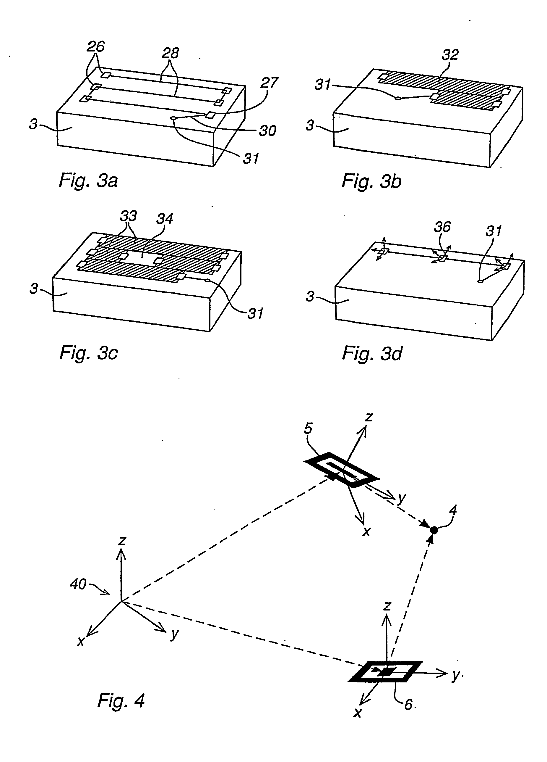
[0016] According to a further embodiment of the invention, the step determining the position of the point comprises: recognizing a first marker within the image, said first marker being positioned in a fixed relation to the object, recognizing a second marker within the image, said second marker being positioned in a fixed relation to a pointing member pointing out the point, determining the position of the point in relation to the object based upon the first and the second marker. This method for determining the position of the point being pointed out by the pointing member does not require any additional measuring equipment for measuring the position of the point besides the two markers.
[0025] According to a further embodiment of the invention, the activating members are arranged on the pointing member. This arrangement makes it easy for the operator to point out the waypoints, record the waypoints, and delete them without releasing the grip of the pointing member.

Problems solved by technology

Either way, the teaching process is time consuming, troublesome, error prone, and in almost all cases requires several iterations before the program is acceptable.
The CAD approach is costly and not always intuitive to use.
The complexity of the CAD-system requires the operator who is programming the robot to have knowledge about computer science.
Another disadvantage with the manual teaching method is that it does not include any visual feedback to the operator, visualizing what has been programmed.
For example, when the robot is to be taught how to paint an object and the entire surface of the object must be covered with colour, it is impossible for the operator, without running the program afterwards, to see if he has missed some part of the surface.
Thus, this method shows the next operation to be performed by the robot, but it does not provide any visual feedback to the operator regarding what he has been programmed.

Method used


Image

  • Method and a system for programming an industrial robot
  • Method and a system for programming an industrial robot
  • Method and a system for programming an industrial robot

Examples


Embodiment Construction

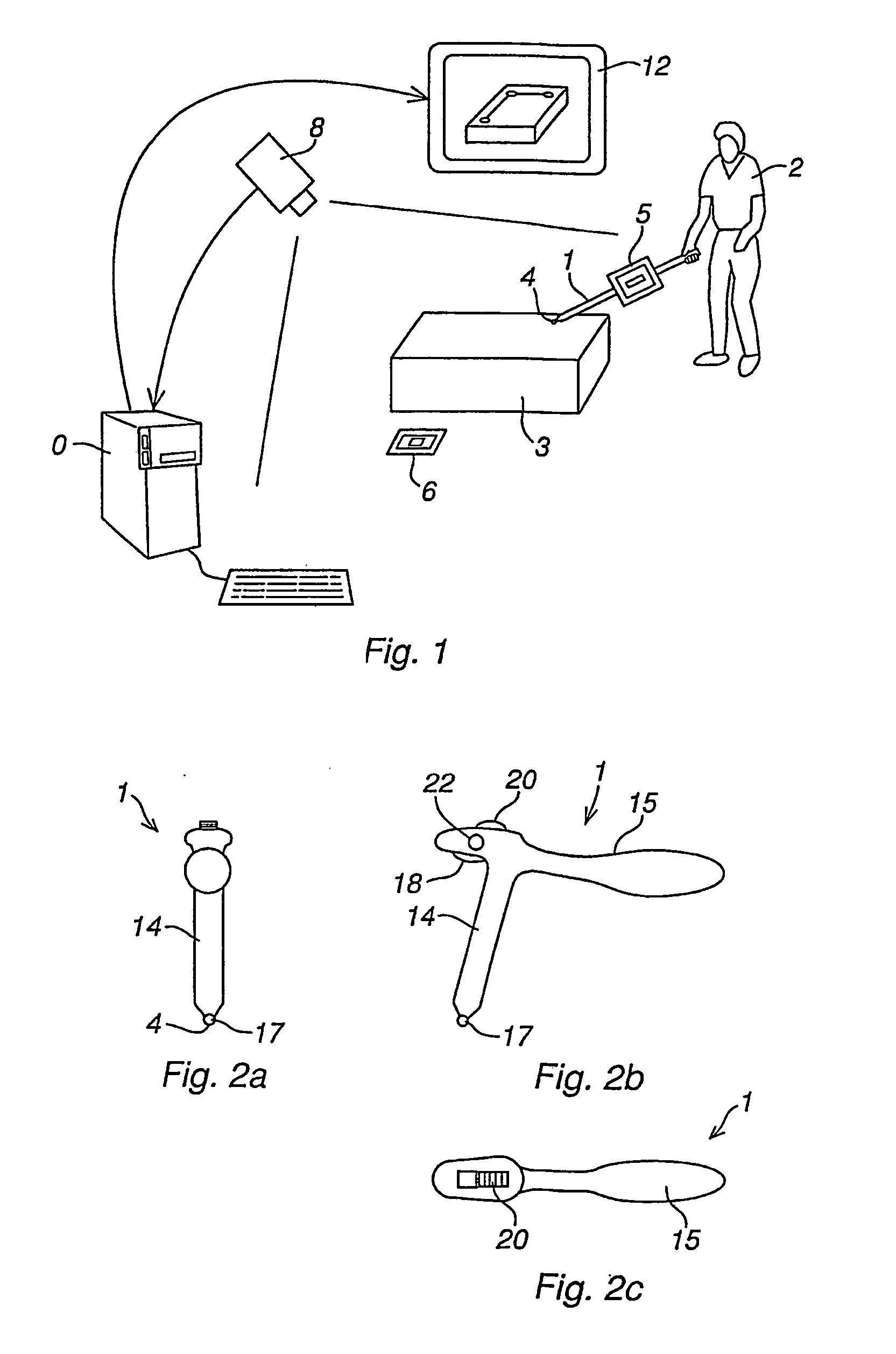
[0034]FIG. 1 illustrates a system for use in connection with programming of an industrial robot according to the present invention. The system comprises a pointing member 1 utilized by a human operator 2 for teaching the robot how to process an object 3. The pointing member can either be the processing tool itself, or preferably a device particularly adapted for the purpose of teaching the processing of the object. The pointing member could, for example, be a pen shaped device or an imitation of the processing tool, such as a paint-gun. The teaching comprises teaching the robot a path including a number of waypoints given in a specific sequence and located on or in the close vicinity of the object 3. Each waypoint comprises the position of a point on or in a close vicinity of the object, the orientation of a processing tool, such as a paintbrush, in the point, and data related to the processing.

[0035] The operator holds the pointing member 1 in his hand and points at the point he w...


PUM


Abstract

A method for programming an industrial robot. The robot is taught a path having waypoints located on or in the vicinity of an object. An image of the object is obtained. Information is obtained about the position of a pointer pointing at points. The position of the points relative to the object is determined. A point being pointed out is stored as a waypoint. A graphical representation is generated of the stored waypoint and the point being pointed out. A view is displayed including the object and the graphical representation. A system includes a pointer for pointing out points on or in the vicinity of the object, a position determiner determines the position of the points relative to the object, a camera delivers an image of the object and the pointer, a graphical generator generates graphics, a display displays a view including the object and graphical representation, and an activator.

Description

FIELD OF THE INVENTION [0001] The present invention relates to a method in connection with programming of an industrial robot, comprising teaching the robot a path which has a number of waypoints located on or in the vicinity of an object to be processed by the robot. The processing of the object could be any type of surface processing application carried out by an industrial robot, such as painting, polishing, grinding, and welding. [0002] The present invention also relates to a computer program product directly loadable into the internal memory of a computer, comprising software code portions for performing the steps of the method according to the invention, when said product is run on a computer. [0003] The present invention also relates to a computer readable medium having a program recorded thereon, where the program is to make a computer perform the steps of the method according to the invention when said program is run on the computer. [0004] The present invention further rel...

Claims


Application Information

Patent Timeline
IPC IPC(8): B25J9/16B25J9/22G05B19/42
CPCB25J9/1664G05B19/42G05B2219/35493G05B2219/45065G05B2219/36479G05B2219/39449G05B2219/36452
Inventor SKOURUP, CHARLOTTEPRETLOVE, JOHN
Owner ABB (SCHWEIZ) AG
Learn More