Honeycomb structure producing method, and honeycomb structure

a honeycomb structure and production method technology, applied in the field of honeycomb structure production methods, can solve the problems of inability to apply the method to large-sized honeycomb structures, affecting the strength of honeycomb structures, and affecting the quality of honeycomb structures

Active Publication Date: 2005-11-17
NGK INSULATORS LTD
View PDF4 Cites 34 Cited by
  • Summary
  • Abstract
  • Description
  • Claims
  • Application Information

AI Technical Summary

Benefits of technology

[0042] [35] A honeycomb structure described in any one of the above [19]-[34], wherein the honeycomb structure is cylindrical and the difference between the maximum diameter and the minimum diameter of the cylindrical honeycomb structure is not more than 1 mm.
[0043] [36] A honeycomb structure d...

Problems solved by technology

However, if honeycomb structures are large-sized, mechanical strength thereof decreases and therefore distortions and damages are apt to occur during use, which necessitates employment of a reinforcing means.
As the reinforcing means, there is a method of disposing an outer wall on the outer peripheral surface of the honeycomb structures, but this method cannot be applied to large-sized honeycomb structures.
For example, there is disclosed a method of providing an outer peripheral wall on the honeycomb structures, followed by firing, but this method gives no consideration to the difference between the proportion of dimensional shrinkage of the outer peripheral wall before and after firing (firing shrinkage percentage) and the proportion of volumetric shrinkage of the inner cell structure (ceramic honeycomb body), and, hence, when the cell structure is made larger in size, distortion is apt to occur during firing due to the difference in proportion of dimensional shrinkage before and after firing, resulting in breakage of the structure (e.g., UM (Utility Model)-B-7-183).
However, according to t...

Method used


Image

  • Honeycomb structure producing method, and honeycomb structure
  • Honeycomb structure producing method, and honeycomb structure
  • Honeycomb structure producing method, and honeycomb structure

Examples


example

[0070] The present invention will be more specifically explained by the following examples, which should not be construed as limiting the invention in any manner.

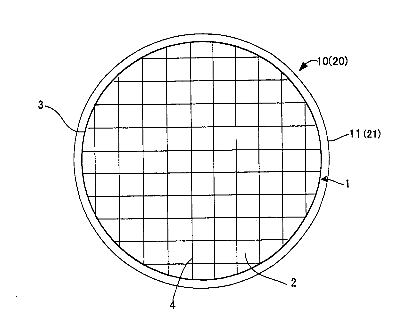
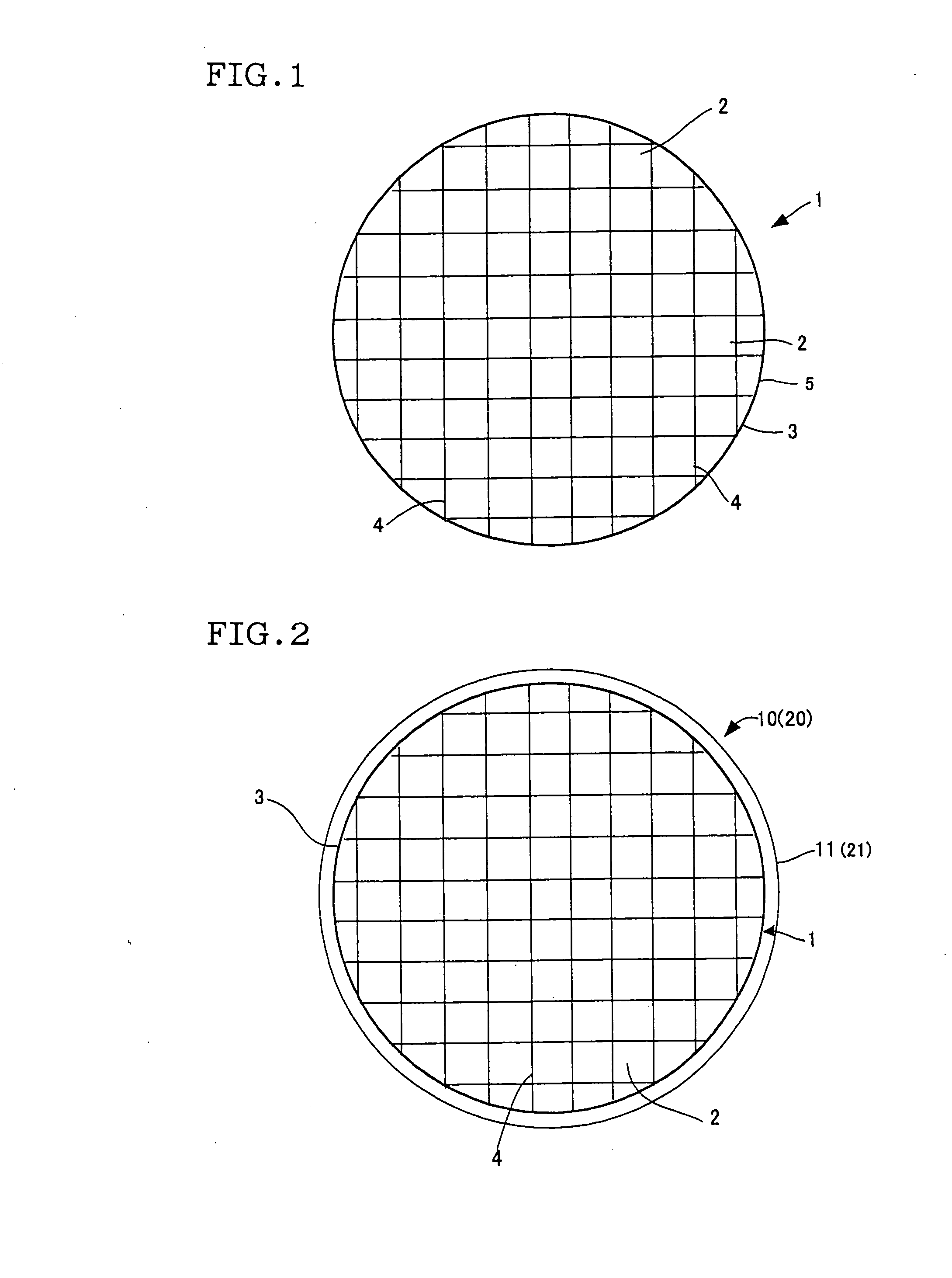
[0071] The inorganic raw materials shown in Table 1 were weighed in accordance with the composition of I shown in Table 2. To 100 parts by mass of the inorganic raw materials were added 4 parts by mass of methyl cellulose, 0.1 part by mass of potassium laurate and 33 parts by mass of water, followed by mixing and kneading to prepare a clay for molding. This was formed into a columnar clay by a vacuum kneading machine, from which a honeycomb (cell structure having outer peripheral wall) was molded by a ram type extrusion molding machine. The resulting honeycomb was dried by a dielectric drying machine and completely dried by a hot-air drying machine. This honeycomb was cut at both end parts to a given length, and fired by keeping at a maximum temperature of 1425° C. for 4 hours to obtain a cell structure mainly composed of ...


PUM

PropertyMeasurementUnit
Fractionaaaaaaaaaa
Fractionaaaaaaaaaa
Fractionaaaaaaaaaa

Abstract

In a method for producing a honeycomb structure 20 which comprises disposing a material for forming outer wall 11 on the outer peripheral surface 3 of a cell structure 1 having a plurality of cells serving as fluid flowing channels to produce a cell structure being provided with a material for forming outer wall 10 and firing the resulting cell structure being provided with a material for forming outer wall 10, wherein a cell structure being provided with a material for forming outer wall 10 in which the absolute value of the difference between the volumetric shrinkage percentage (firing shrinkage percentage) before and after firing of the cell structure 1 and the firing shrinkage percentage of the material for forming outer wall 11 is not more than 0.5% is produced and fired. There is provided a method for producing a honeycomb structure which comprises providing an outer wall on the outer peripheral surface and firing it, according to which the outer wall hardly cracks during firing and high-strength and large-sized honeycomb structure can be produced, and further provided is a high-strength and large-sized honeycomb structure in which the outer wall hardly cracks during firing.

Description

TECHNICAL FIELD [0001] The present invention relates to a method for producing a high-strength and large-sized honeycomb structure, and a high-strength and large-sized honeycomb structure. BACKGROUND ART KBackground Art [0002] Honeycomb structures comprising ceramics are used for collecting dusts and other particulate materials contained in exhaust gases discharged from automobiles and exhaust gases generated upon incineration of waste products, for purification of the exhaust gases by removing NOx, CO, HC, etc. using supported catalysts or for purification of high-temperature exhaust gases discharged from production steps in various manufacturing and mining industries. The honeycomb structures are structures formed for collecting and removing particulate materials contained in dust-containing fluids. They have many fluid flowing cells which are partitioned with partition walls and which pierce through the honeycomb structures in axial direction, and the partition walls of the fluid...

Claims


Application Information

Patent Timeline
IPC IPC(8): F01N3/02B01D39/20B01D46/00B01J35/04B28B11/00C04B38/00
CPCB01D39/2068B01J35/04C04B38/0006C04B2111/0081C04B2235/9607C04B2235/9615Y10T428/24149C04B35/195C04B38/0077C04B41/5024
Inventor NOGUCHI, YASUSHINAKAMURA, TOMOO
Owner NGK INSULATORS LTD
Why Eureka
Try Eureka