Method of making a glass-ceramic article

a glass-ceramic and glass-ceramic technology, applied in glass making apparatus, induction heating, induction heating apparatus, etc., can solve the problems of glass-ceramic cooking surface up to about 700° c. and more can occur, scratching, increase, etc., and achieve high mechanical stability

a glass-ceramic and glass-ceramic technology, applied in glass making apparatus, induction heating, induction heating apparatus, etc., can solve the problems of glass-ceramic cooking surface up to about 700° c. and more can occur, scratching, increase, etc., and achieve high mechanical stability

US20050255983A1Active Publication Date: 2005-11-17SCHOTT AG

Image

  • Method of making a glass-ceramic article
  • Method of making a glass-ceramic article
  • Method of making a glass-ceramic article

Examples


Embodiment Construction

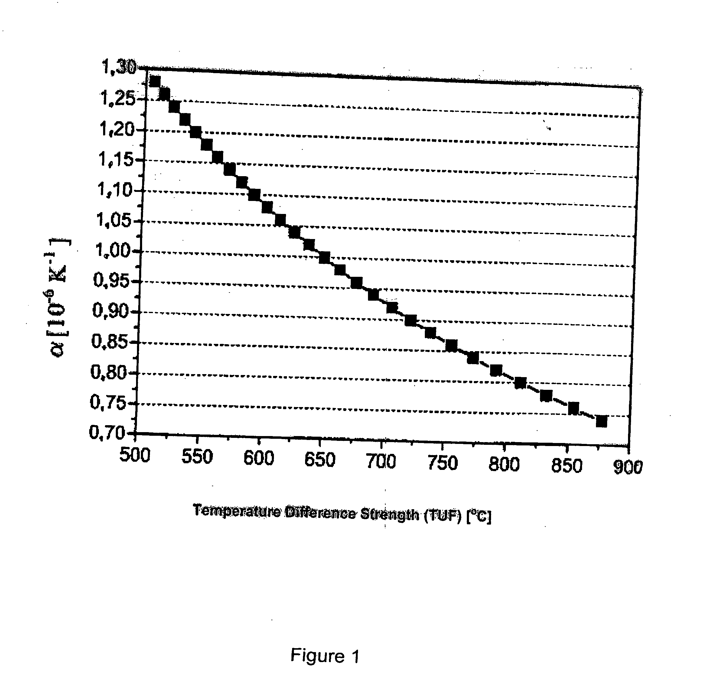
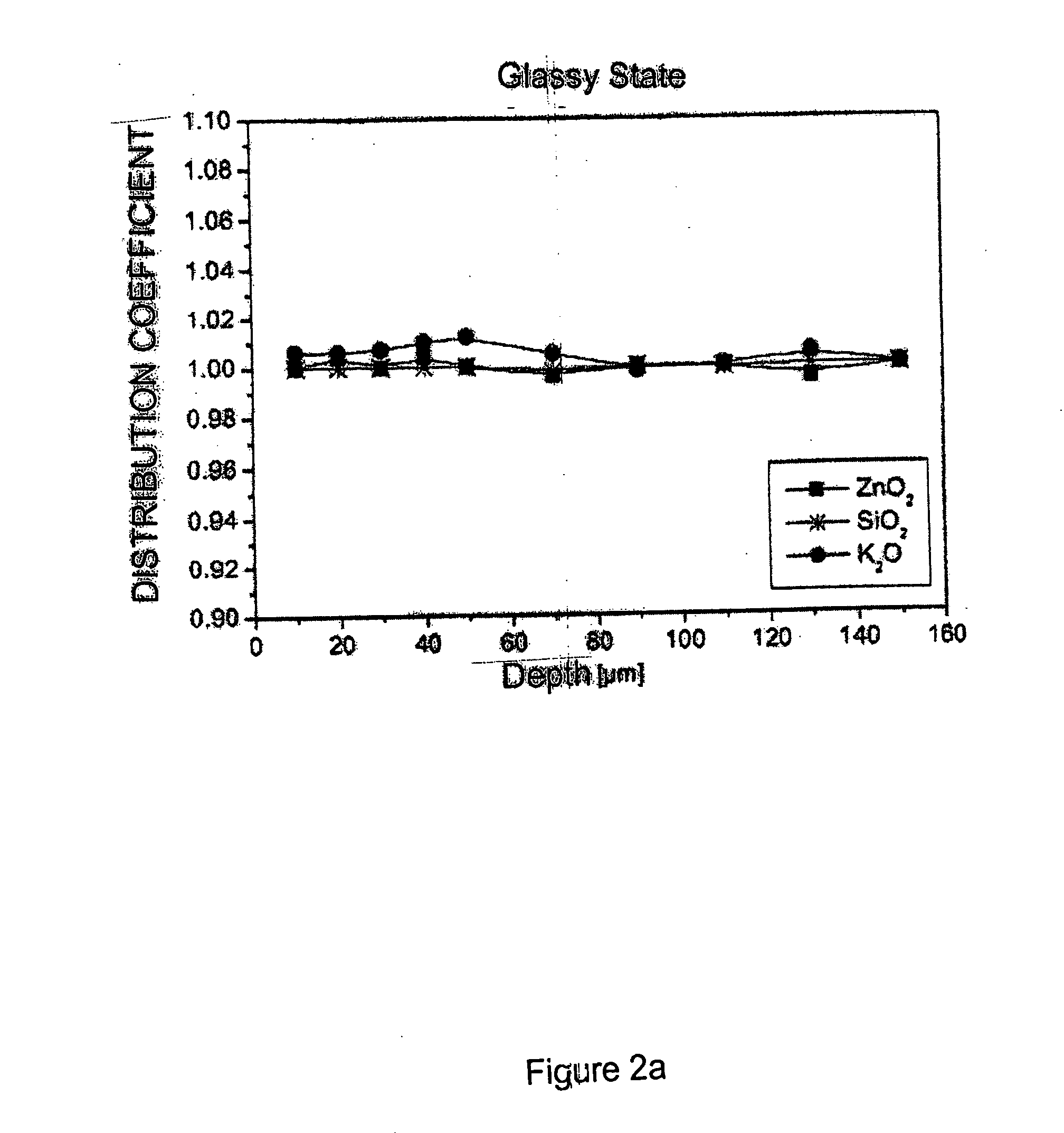
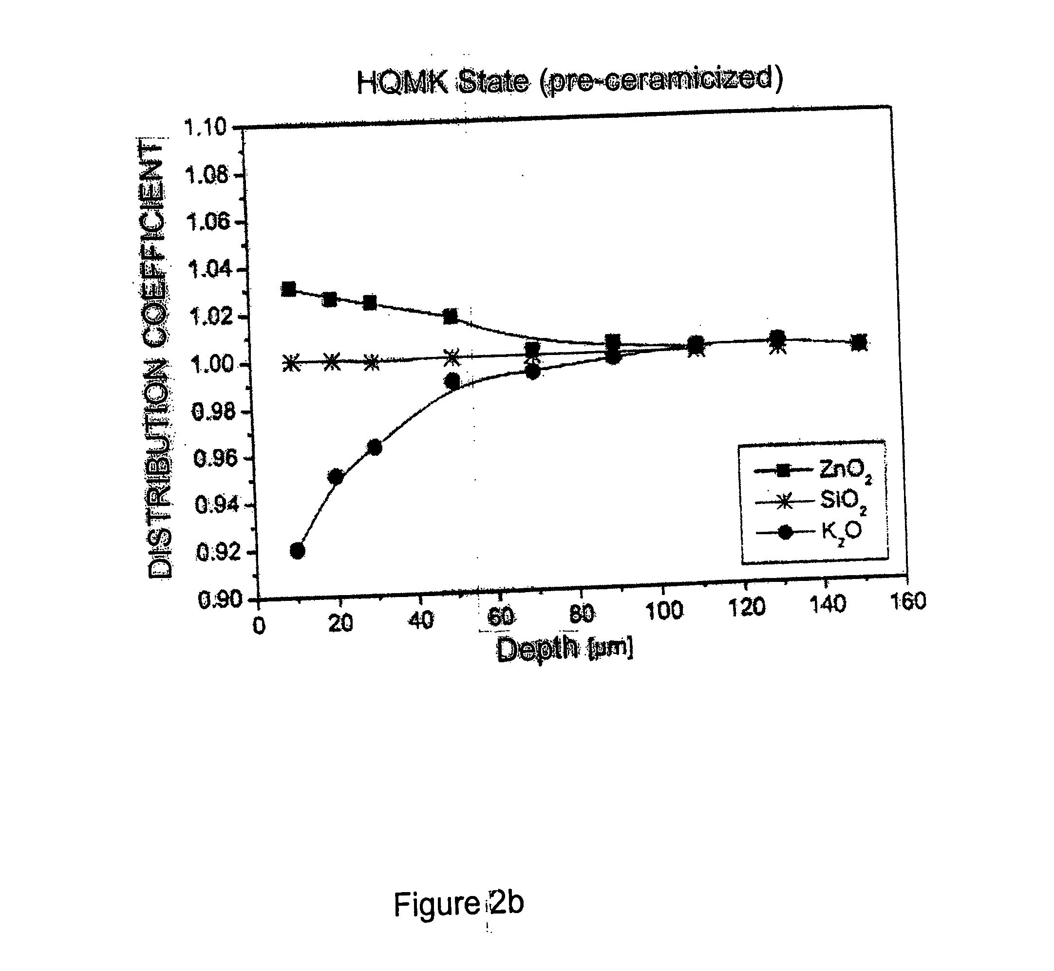
[0043] The temperature difference resistance (TUF) is increased with the help of the method according to the invention. Glass-ceramics with a TUF of up to about 750° C. can be made with the method according to the invention. Chemical concentration gradients for KMK glass-ceramics with different high TUF values, which were measured by X-ray fluorescence analysis, are illustrated in FIGS. 2a to 2d.

[0044] The distribution coefficients (defined as the ratio of concentration at the surface to bulk, wherein the concentration in bulk is measured at a constant depth greater than 150 μm) of zinc oxide, silicon dioxide and potassium oxide in the glass state at various depths greater than 160 μm are illustrated in FIG. 2a. These same distribution coefficients are shown in FIG. 2b for the pre-ceramicized state, i.e. measured in the high quartz mixed crystal phase. In contrast to the glass state, in which the distribution coefficients for all three components is essentially a constant value equ...


PUM

PropertyMeasurementUnit
Temperatureaaaaaaaaaa

Abstract

The method produces a glass-ceramic article substantially in the form of a plate with improved high temperature difference resistance or strength. The glass-ceramic article contains keatite mixed crystals (KMK) or high quartz mixed crystals (HQMK) as well as the keatite mixed crystals (KMK). The method includes heating a glass-ceramic in a high quartz mixed crystal state to form the keatite mixed crystals with a heating rate of 20 K / min to 150 K / min, preferably more than 15 K / min, especially preferably more than 20 K / min. These high heating rates increase the temperature difference resistance.

Description

BACKGROUND OF THE INVENTION [0001] 1. Field of the Invention [0002] The present invention relates to a method of making a glass-ceramic article having a keatite mixed crystal phase in at least a part of its interior. [0003] 2. Related Art [0004] It is known that glasses from the Li2O— Al2O3—SiO2 system may be converted into glass-ceramic articles with high quartz mixed crystals (HQMK) and / or keatite mixed crystals (KMK) as principal crystal phase. The making of these glass-ceramics occurs in several stages. After melting and hot shaping the glass is usually cooled at temperatures in the region of the transformation temperature (Tg), in order to remove thermal stresses. After that the material is further cooled to room temperature. [0005] The starting glass is crystallized with a second controlled temperature treatment and converted into a glass-ceramic article. This ceramicizing occurs in a multi-stage temperature process, in which crystal nuclei are produced by nuclei formation at ...

Claims


Application Information

Patent Timeline
17 Nov 2005
Publication
US20050255983A1
IPC
C03B32/02; H05B6/12; C03C10/00; C03C10/14
CPC
C03B32/02; C03C10/0054; C03C10/0045; C03C10/0036
Inventors
BECKER, OTMAR; GABEL, FALK