
Method and apparatus to increase the usable memory capacity of a logic simulation hardware emulator/accelerator

a logic simulation and emulator technology, applied in the field of methods and apparatus, can solve the problems of insufficient simulation speed, high initial production cost of circuit chips, and large bottlenecks in the design process, and achieve the effect of efficient utilization of physical memory

Inactive Publication Date: 2005-11-17
IBM CORP
View PDF4 Cites 17 Cited by
  • Summary
  • Abstract
  • Description
  • Claims
  • Application Information

AI Technical Summary

Benefits of technology

[0014] The present invention provides a method, apparatus and computer readable program product for transforming modeled memory elements within a logic simulation hardware emulator / accelerator to more efficiently utilize physical memory.

Problems solved by technology

As circuit complexity increases and the time to market shortens, inadequate simulation speed becomes a major bottleneck in the design process.
Thus, the necessity and usefulness of such devices has increased enormously with growth in the complexity of integrated circuits.
However, it is noted that the construction of such masks and the initial production of circuit chips is expensive.
Any passage of a given device having the prescribed logic functionality though such a foundry is an expensive and time consuming process which clearly should be undertaken only once.
Debugging logic errors deep inside a logic chip can be extremely difficult because of very limited observability.
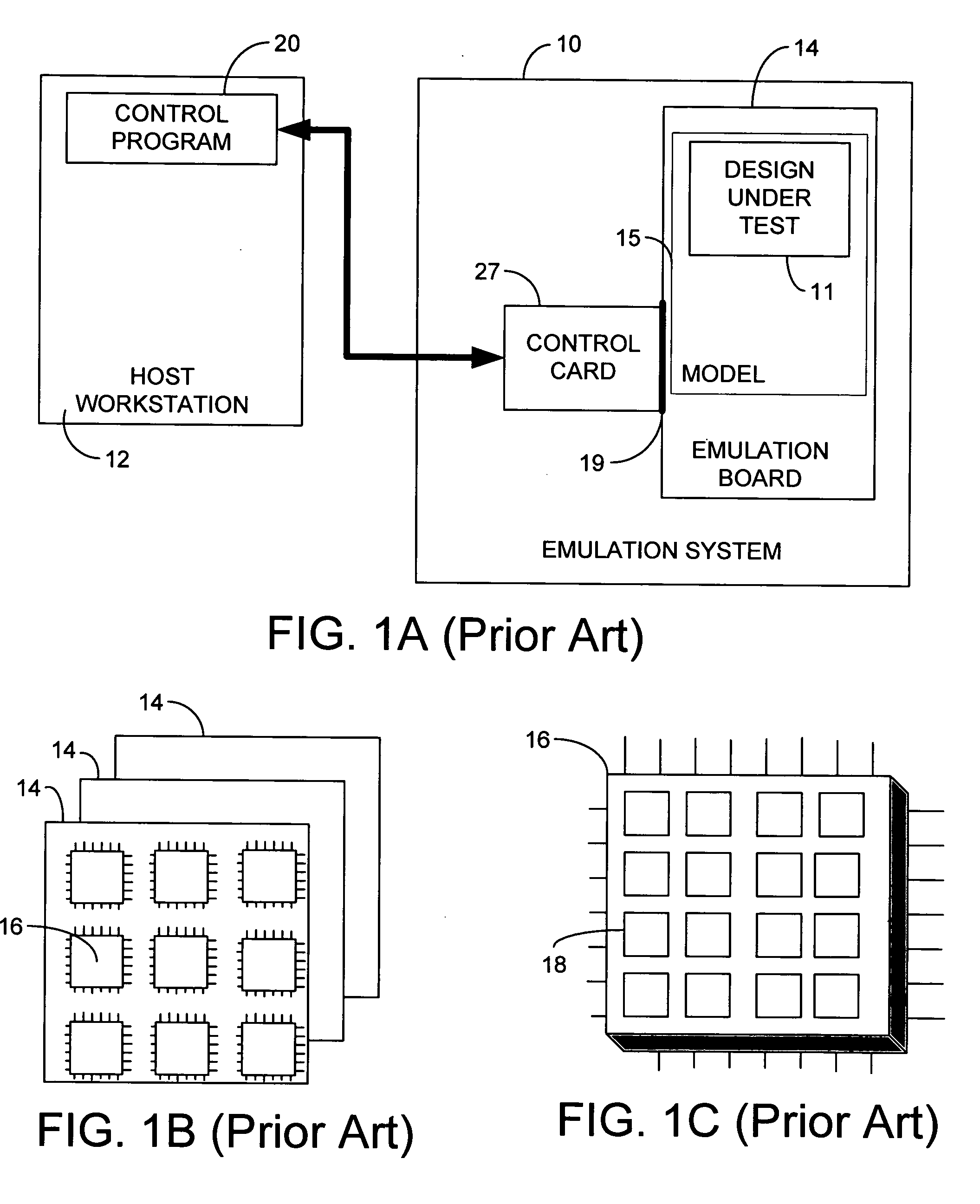
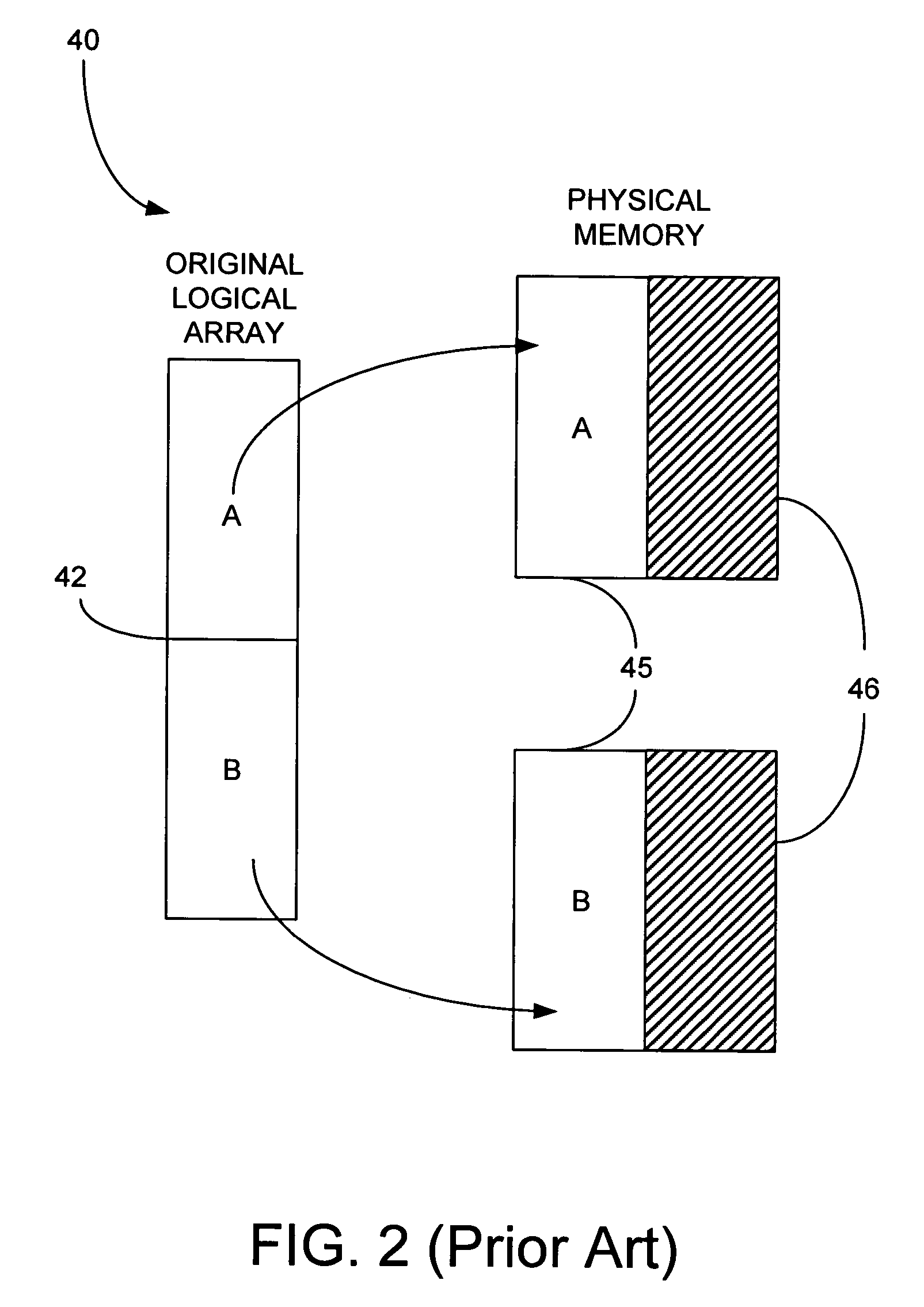
The physical memory resources of the emulation system 10 can be a limiting factor in the success of building a logic model, depending on the efficiency of mapping the logical arrays to the physical memories.
Inefficiencies occur when the width of the logical array is not an even multiple of the width of the physical memory.
The greatest waste occurs when logical arrays are very narrow compared to the width of the physical memories.

Method used


Image

  • Method and apparatus to increase the usable memory capacity of a logic simulation hardware emulator/accelerator
  • Method and apparatus to increase the usable memory capacity of a logic simulation hardware emulator/accelerator
  • Method and apparatus to increase the usable memory capacity of a logic simulation hardware emulator/accelerator

Examples


Embodiment Construction

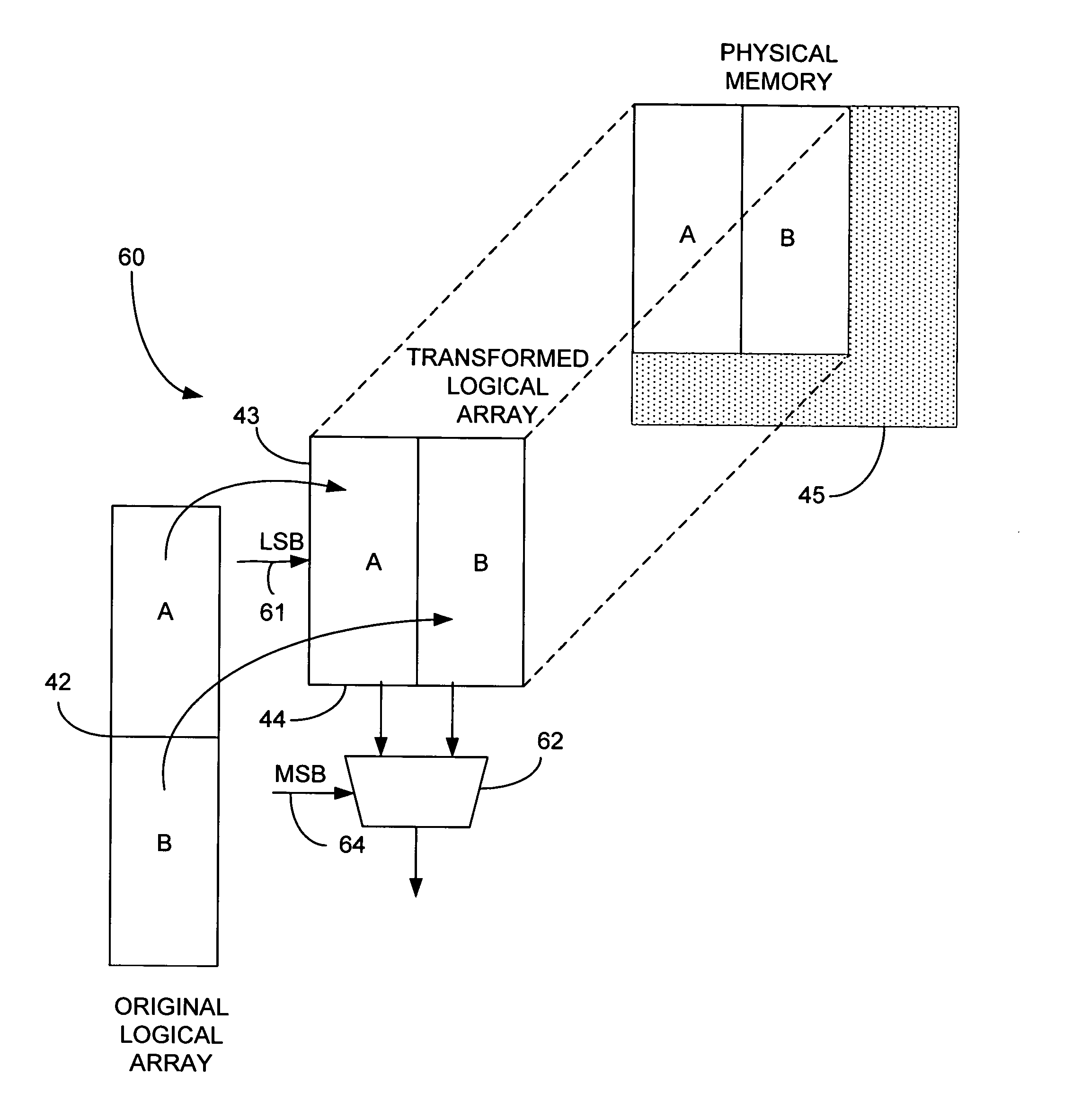
[0037] The present invention provides a method, apparatus and program product which effectively increases the usable memory capacity of a logic simulation hardware emulator without adding physical memory. The solution is comprised of additional logic synthesis algorithms being run during model build to transform logical arrays for a better fit into physical memory dimensions, plus additional software routines executed at runtime to automatically resolve the new array organization and transparently provide read and write access to logical array data from simulation software.

[0038] Turning to the Drawings, wherein like numbers denote like parts throughout the several views, FIG. 3 illustrates how the same original logical array as shown in prior art FIG. 2 can be transformed into a new, transformed array which, when mapped to a physical memory, will utilize half of the previously consumed physical memory space, thus effectively doubling the memory capacity of the emulation system. To...


PUM


Abstract

A method, apparatus and program product are provided for increasing the usable memory capacity of a logic simulation hardware emulator. The present invention performs an additional logic synthesis operation during model build to transform an original logical array within a logic model into a transformed logical array, such that a row within the transformed logical array includes a plurality of merged logical array rows from the original logical array. The invention further modifies read and write port logic surrounding the transformed logical array during the logic synthesis operation to support read and write accesses during model emulation run time.

Description

FIELD OF THE INVENTION [0001] The present invention relates generally to logic simulation hardware emulation, and more specifically to the transforming of modeled memory elements to more efficiently utilize memory in a logic simulation hardware emulator / accelerator. BACKGROUND OF THE INVENTION [0002] Design verification is essential to virtually any very large scale integration (VLSI) design project. One of the popular verification methods is logic simulation. Logic simulation software reports on how a circuit under design responds to a sequence of input vectors, so the designer can judge whether the circuit behaves as expected over an input sequence. The more vectors simulated, the greater confidence the designer has in the correctness of the designing circuit. [0003] As circuit complexity increases and the time to market shortens, inadequate simulation speed becomes a major bottleneck in the design process. As a result, several special purpose machines have been built to simulate / ...

Claims


Application Information

Patent Timeline
IPC IPC(8): G06F9/455G06F17/50
CPCG06F17/5027G06F30/331
Inventor GOODING, THOMAS MICHAELMUSSELMAN, ROY GLENN
Owner IBM CORP
Learn More