System and method for monitoring and controlling energy usage

Active Publication Date: 2005-11-24
LINCOLN GLOBAL INC
View PDF7 Cites 154 Cited by
  • Summary
  • Abstract
  • Description
  • Claims
  • Application Information

AI Technical Summary

Benefits of technology

[0012] In another and/or alternative aspect of the present invention, there is provided a system and method to control energy consumption of one or more power consuming devices wherein the controller for such devices manages the power consumption by such devices based upon one or more control criteria. The control criteria can include, but is not limited to, the energy charge per kilowatt hour of energy used based upon the time of day and/or time of year, the demand charge for the maximum rate of energy used during an energy billing period, the priority or precedence of operation of a particular energy consuming device in a production process, production criteria for a particular energy consuming device in a production process, maximum allowable energy consumption for a particular time period, actual and/or anticipated energy costs during a particular period, the time of day, the month, inventory levels, production quotas, malfunctioning equipment, etc. As can be appreciated, the energy control system can be as simple as maintaining the energy consumption of a plurality of devices below a certain energy threshold or can be as complicated as controlling a production line of a manufacturing facility based upon inventory levels, production quotas, times of the day or month, anticipated power usage of one or more devices when activated, anticipated amount of power usage decrease when one or more devices is deactivated, etc.
[0013] In accordance with still another and/or alternative aspect of the present invention, there is provided a network architecture that is used

Problems solved by technology

The energy cost for businesses continues to rise.
The energy costs for businesses are significant especially in the industrial sector wherein hundreds or thousands of kilowatt hours of power may be used daily.
These energy costs are generally fixed costs that are passed on to the consumer by increasing the cost of a manufactured product.
However, the increased amount of machinery used to automate a particular manufacturing has resulted in increased energy usage.
Although energy usage and cost has become an increased concern for residential, commercial and industrial consumers, there have been few options to reduce this cost.
Billing terminology and contract terms can be complex and are often misunderstood.
The time of day when consumption occurs may also influence utility costs.
Peak supply hours for a utility generally occur between the hours of 8 a.m. and 9 p.m. and the cost of energy to consumers during this time may be nearly double the off-peak cost.
This cost different exists because it costs the power company more to serve the higher-demand customer, since power companies must have more facilities in place to serve the higher demand at any given moment.
In many parts of the country, utility capacity is highly stressed and over the last ten years, savvy utility companies have offered “cost reductions” to contract purchasers that were based on holding demands constant and have a very high penalty for additional growth.
In some contracts where the demand charges are very high, the energy charge is actually a negative value meaning that the utility will pay the consumer to burn more power.
This occurs when equipment inefficiently converts supplied power to other uses.
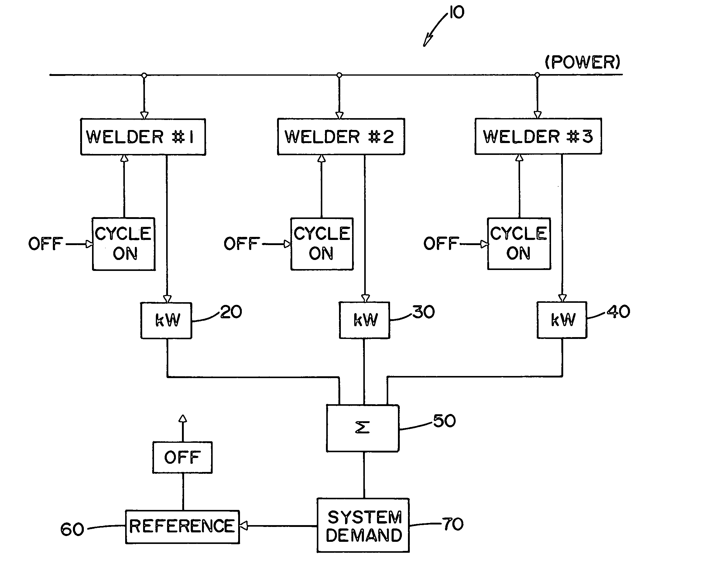
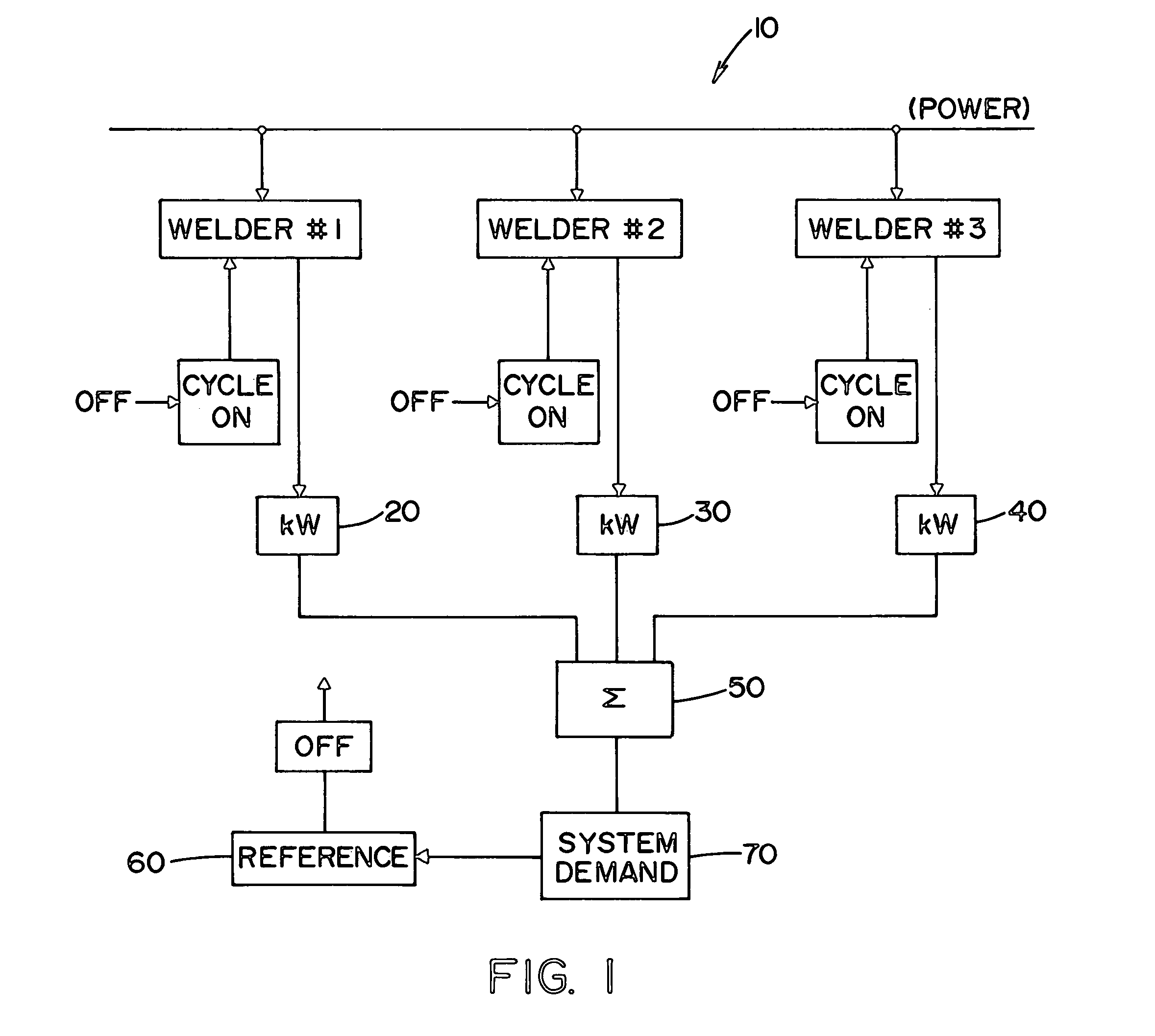
Industrial consumers that utilize electric arc welders in an assembly process to manufacture products (e.g., automotive i

Method used


Image

  • System and method for monitoring and controlling energy usage
  • System and method for monitoring and controlling energy usage
  • System and method for monitoring and controlling energy usage

Examples


Embodiment Construction

[0028] Referring now to the drawings, wherein the showings are for the purpose of illustrating the preferred embodiments of the invention only and not for the purpose of limiting the same, FIG. 1 illustrates an energy monitoring system 10 in accordance with the present invention. FIG. 1 illustrates three welders, welder #1, welder #2 and welder #3 being supplied power form a power source. As can be appreciated more welders or less welders can be monitored by the energy monitor system of the present invention. Typically, the power supplied to the welders is provided a local power supplier; however, some or all of the power could be supplied by cogeneration at a particular facility. Each of the welders are connected with or integrated with an energy monitoring device 20, 30, 40. The energy monitoring devices monitor the amount of energy consumed by each welder in kW over a particular period of time. The amount of energy being used by each welder is transmitted to a summation device 50...


PUM

PropertyMeasurementUnit
Energyaaaaaaaaaa

Abstract

A welding control system to monitor the energy consumption of a plurality of welders. The welding control system controls the operation of one or more welders based upon the energy information received from one or more energy monitoring devices.

Description

INCORPORATION BY REFERENCE [0001] U.S. Pat. Nos. 6,486,439 and 6,624,388 are incorporated herein by reference to illustrate a networked welding system that can be use in accordance with the present invention.[0002] The present invention relates generally to the monitoring and controlling of equipment based upon actual and / or anticipated energy usage, and more particularly to a system and method of providing a welding architecture and / or a network architecture that enables control of one or more welders based upon actual and / or anticipated energy usage of the welders connected to the network. BACKGROUND OF THE INVENTION [0003] The energy cost for businesses continues to rise. The energy costs for businesses are significant especially in the industrial sector wherein hundreds or thousands of kilowatt hours of power may be used daily. These energy costs are generally fixed costs that are passed on to the consumer by increasing the cost of a manufactured product. In a global economy, ma...

Claims


Application Information

Patent Timeline
IPC IPC(8): B23K9/095
CPCB23K9/0953
Inventor BLANKENSHIP, GEORGE D.MASON, SETH
Owner LINCOLN GLOBAL INC
Why Eureka
Try Eureka