Multimode fiber optical fiber transmission system with offset launch single mode long wavelength vertical cavity surface emitting laser transmitter

Active Publication Date: 2005-11-24
OPTICAL COMM PRODS
View PDF27 Cites 17 Cited by
  • Summary
  • Abstract
  • Description
  • Claims
  • Application Information

AI Technical Summary

Benefits of technology

[0008] In recent years, significant effort has gone into developing Long Wavelength Vertical Cavity Surface Emitting Lasers (VCSEL's). One long wavelength VCSEL material system specifically in current development is based on InGaAsN technology, but other material systems are also possible. These long wavelength VCSEL's now realize the low drive current and ease of packaging benefits previously realized with shorter wavelength VCSEL structures and are a significant technical advance from the prior art shorter wavelength VCSELs. The new long wavelength VCSEL's have been designed with efficient coupling into single mode fiber (SMF) in mind and have small, substantially circular emission spots in the range of 3 to 10 μm diameter and more preferably 6 to 7 μm diameter. These VCSEL devices also have a small numerical aperture (˜0.1) that provides the opportunity for precise alignment and direct butt coupling to single mode fibers in some circumstances. The near parallel optical emission profile of these devices enables efficient optical coupling into single mode fiber where the core diameter is typically 9 um. Furthermore, the long wavelength VCSELs have been specifically designed to operate in a single longitudinal mode at high power levels and are now ready to replace the traditional Fabry Perot edge emitters commonly used at long wavelengths such as 1300 nm.
[0011] The ideal offset launch has been found experimentally to be 20 um on 62.5 um MMF and this has been reliably achieved by translating the VCSEL device laterally from the center axis of the multimode fiber by a fixed amount and then fixing the VCSEL in place. This is an easy process in manufacture because of the VCSEL package configuration, and negates the need for a mode conditioning patchcord. The emission size of the long wavelength VCSELs, which were developed for single mode fiber applications, is fortuitously ideal for providing a restricted offset launch on multimode fibers. This novel application of long wavelength VCSEL technology to the problem of limited multimode fiber bandwidth now enables the manufacture of very low cost transmitters capable of distances previously unattainable.
[0014] the provision of a new launching technique which removes the need for a mode conditioning patchcord specified in the standards;

Problems solved by technology

In fact, approximately 10% of installed fiber can suffer bandwidth collapse with long wavelength laser transmitters when launched on axis or with a typical offset of 3 to 7 um for a multimode fiber connector.
This has been a serious problem in the past, and has been the focus of many experts in this area for the past 15 years.
However, practical use of the system was discounted due to power limitations of the VCSEL.

Method used


Image

  • Multimode fiber optical fiber transmission system with offset launch single mode long wavelength vertical cavity surface emitting laser transmitter
  • Multimode fiber optical fiber transmission system with offset launch single mode long wavelength vertical cavity surface emitting laser transmitter
  • Multimode fiber optical fiber transmission system with offset launch single mode long wavelength vertical cavity surface emitting laser transmitter

Examples


first embodiment

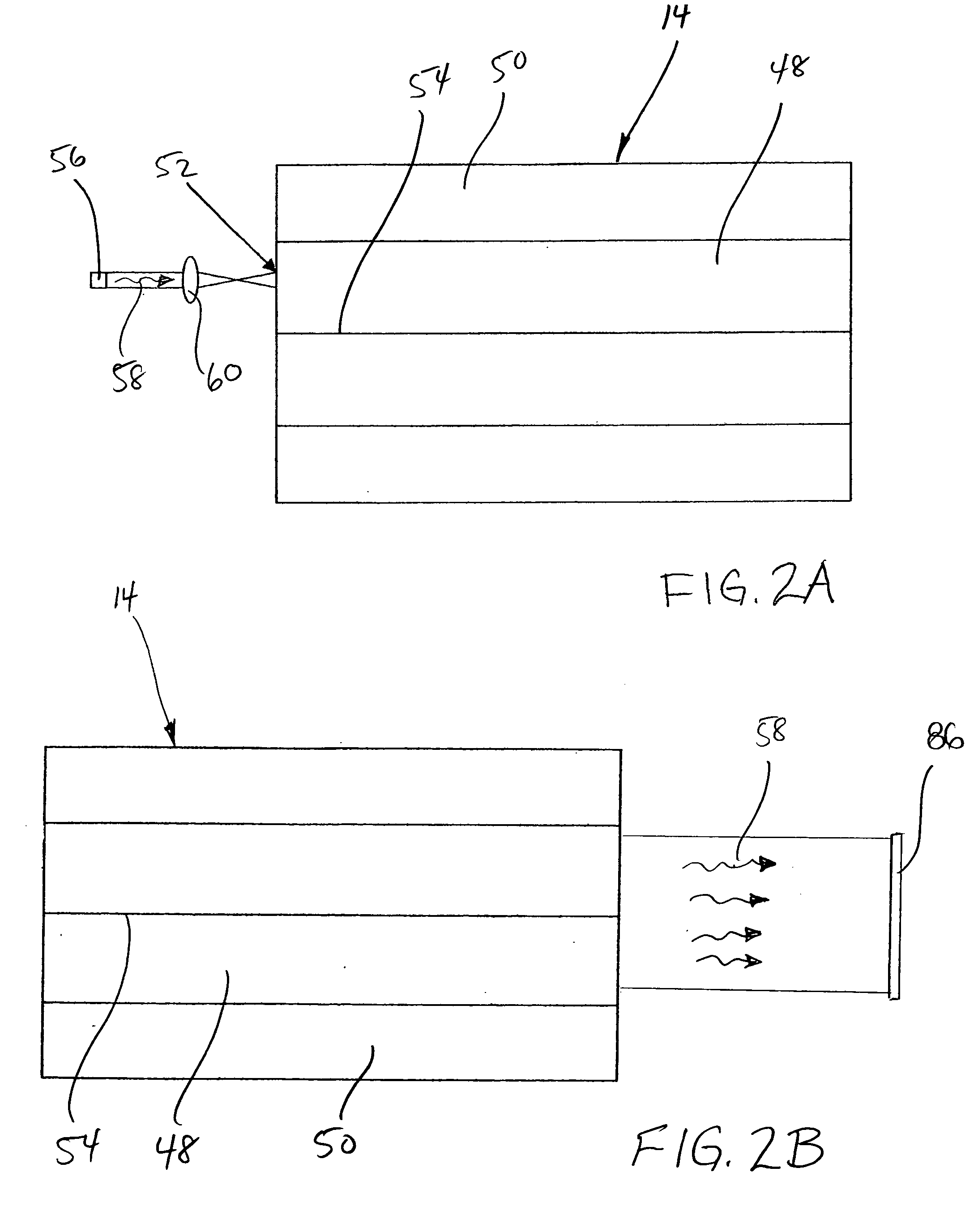
[0038] Turning to FIGS. 2A and 2B, a schematic diagram of the offset launch configuration is illustrated wherein the VCSEL transmission signal 58 is offset launched into the core 50 of the multimode fiber 14 with the help of a lens 60 to focus the laser output. The lens 60 operates to focus and size the launch beam 52 at the offset launch point on the end face of the fiber 14. In this embodiment, both the VCSEL 56 and the lens 60 are positioned offset from the fiber axis 54.

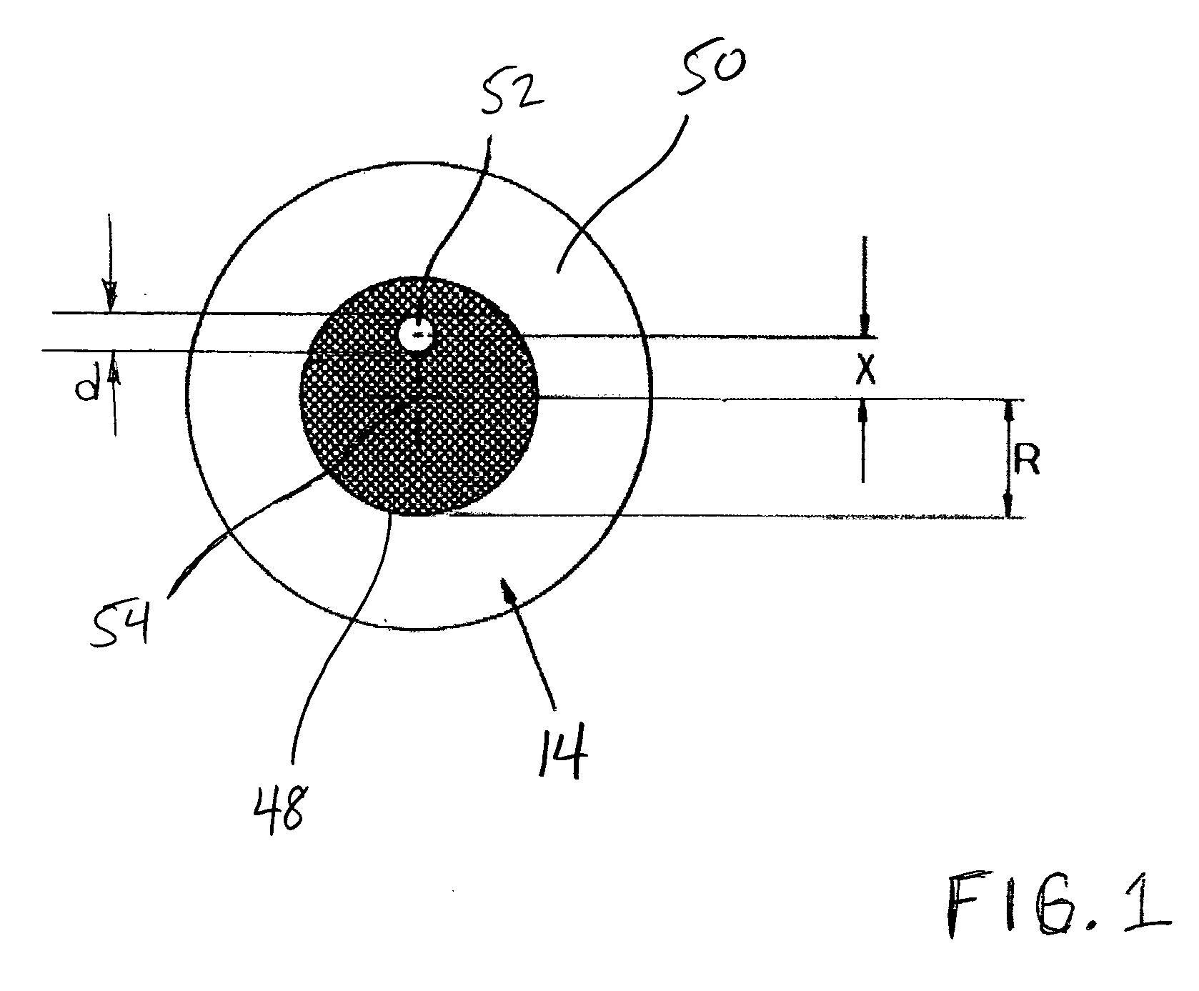
[0039] The ideal offset launch has been found experimentally to be 20 um on 62.5 um MMF and this has been reliably achieved by translating the VCSEL device 56 laterally from the center axis 54 of the multimode fiber 14 by a fixed amount and then fixing the VCSEL 56 in place. This is an easy process in manufacture and negates the need for a mode conditioning patchcord.

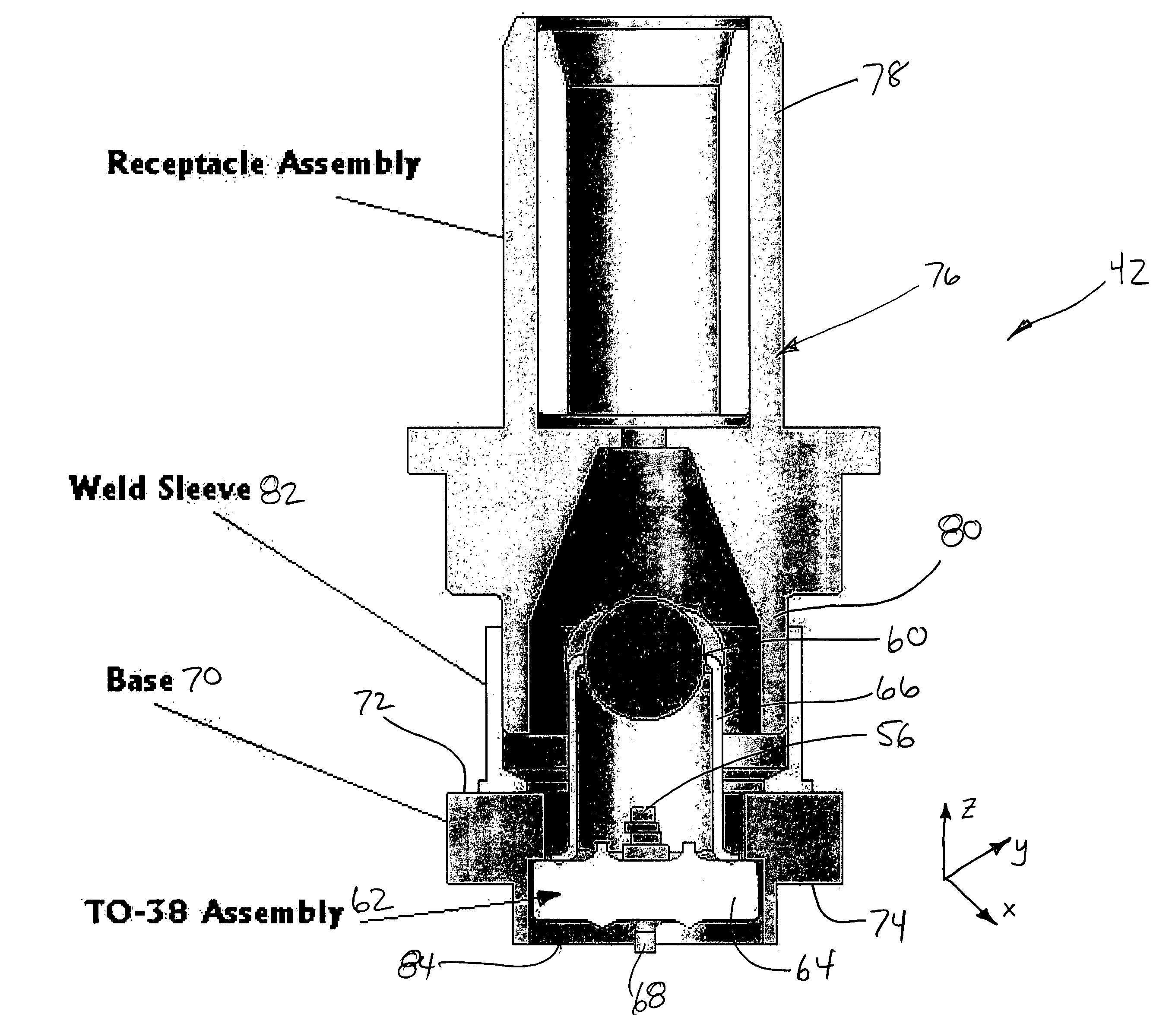
[0040] Turning to FIG. 3, the VCSEL 54 and lens 60 are assembled into a TO-38 package generally indicated at 62. The TO-38 package 62 including a h...

second embodiment

[0045] In a second embodiment as shown in FIG. 8, the VCSEL 56 is mounted normal to the end surface of the fiber 14, and the transmission beam 58 is launched directly into the core 48 at an offset of approximately 20 μm from the optical axis 54 of the core 48. In this particular embodiment, the transmission signal 58 is launched directly into the core 48 of the multimode fiber 14 without an intermediate collecting element, i.e. lens 60. More specifically, the TO-38 package 62 is provided with a window (not shown) rather than the lens at the top of the can enclosure 66, and the TO-38 package 62 is mounted immediately adjacent to the end surface of the multimode fiber 14, i.e. eliminating the extra distance required for the focal length of the lens 60. This arrangement is advantageous for simplifying manufacture of the TO-38 package 62 as there is no need to optically align a lens 60 with the VCSEL 56. Furthermore, the length of the entire transmitter optical subassembly 42 would be s...


PUM


Abstract

A multimode fiber optical fiber transmission system includes an improved configuration for launching a single mode long wavelength transmission signal into existing multimode optical fiber networks. More specifically, the invention utilizes new single mode long wavelength VCSEL devices to realize a novel transmitter / transceiver for multimode fiber links where offset launch with controlled mode conditioning is achieved without the use of a mode conditioning patchcord, and in some embodiments, without the use of any collecting or focusing elements.

Description

CROSS-REFERENCE TO RELATED APPLICATIONS AND CLAIM OF PRIORITY [0001] This application claims the priority benefit of U.S. Provisional Patent Application No. 60 / 472,278, filed May 21, 2003, entitled “MULTIMODE FIBER OPTICAL FIBER TRANSMISSION SYSTEM WITH OFFSET LAUNCH SINGLE MODE LONG WAVELENGTH VERTICAL CAVITY SURFACE EMITTING LASER TRANSMITTER”.BACKGROUND OF THE INVENTION [0002] The present invention relates to optical fiber transmission systems and more particularly to an improved configuration for launching a single mode long wavelength transmission signal into existing multimode optical fiber networks. [0003] Much of the installed based of optical fiber consists of multimode fiber. The problem addressed by this invention is that a significant amount of the installed multimode fiber base consists of inferior quality fiber where the bandwidth associated with the Over-Fill Launch (OFL) condition is not realized. In fact, approximately 10% of installed fiber can suffer bandwidth col...

Claims


Application Information

Patent Timeline
IPC IPC(8): G02B6/32G02B6/38G02B6/42H01S3/08
CPCG02B6/3893G02B6/4206H01S5/02284G02B6/4292G02B6/4246H01S5/02251
Inventor JENKINS, DAVIDPARK, CHRISTOPHER
Owner OPTICAL COMM PRODS
Why Eureka
Try Eureka