System, method, and apparatus for producing high efficiency heat transfer device with carbon nanotubes

a carbon nanotube and heat transfer technology, applied in lighting and heating devices, instruments, transportation and packaging, etc., can solve the problems of existing methods, inability to meet the requirements of heat transfer, so as to improve the heat transfer capability of the final device, the effect of increasing the surface area

Inactive Publication Date: 2005-11-24
LOCKHEED MARTIN CORP
View PDF17 Cites 82 Cited by
  • Summary
  • Abstract
  • Description
  • Claims
  • Application Information

AI Technical Summary

Benefits of technology

[0009] One embodiment of a system, method, and apparatus of the present invention for producing a high efficiency heat transfer device utilizes carbon nanotube deposits. The carbon nanotubes, which may be single-walled, multi-walled, or other types of structures, are formed directly on the heat transfer device substrate and replace conventional cooling fins. The carbon nanotubes grow in a substantially perpen

Problems solved by technology

Heat transfer is a critical issue in aeronautic and space systems.
However, the production of swcnt is substantially limited to an experimental scale with some production rates being on the order of only grams per day.
There are also a number of problems with these existing, prior art methods.
As a result, the rates of production are relatively low, with some methods generating only enough product to scarcely conduct laboratory testing on the end product.
Consequently, it would be very difficult if not impossible to scale these methods up to industrial quantity production levels.
Furthermore, these production methods result in a batch of material that must

Method used


Image

  • System, method, and apparatus for producing high efficiency heat transfer device with carbon nanotubes
  • System, method, and apparatus for producing high efficiency heat transfer device with carbon nanotubes
  • System, method, and apparatus for producing high efficiency heat transfer device with carbon nanotubes

Examples


Embodiment Construction

[0029] U.S. patent application Ser. No. 10 / 455,767, filed Jun. 5, 2003, and entitled, “System, Method, and Apparatus for Continuous Synthesis of Single-Walled Carbon Nanotubes,” is incorporated herein by reference.

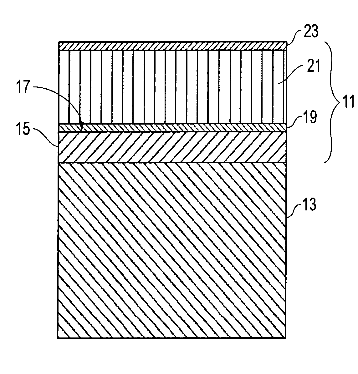
[0030] Referring to FIG. 1, one embodiment of an apparatus or heat transfer device 11 for dissipating heat from an object 13 is shown. For example, device 11 may comprise hollow tubing 15 for conducting heat away from liquid 13 that flows through it, or a solid apparatus 15 that is mounted to a solid object 13. The device 11 comprises a base or substrate 15 having an outer surface 17 and is adapted to be mounted to or in close contact with the object 13. When the object 13 generates or dissipates heat, the device 11 conducts the heat away from the object 13. The substrate may be formed from a thermally conductive material such as iron, graphite, copper, or bronze.

[0031] The device 11 has a catalyst 19 on the outer surface 17 of the substrate 15. The catalyst may be a tra...


PUM

PropertyMeasurementUnit
Thicknessaaaaaaaaaa
Thicknessaaaaaaaaaa
Thicknessaaaaaaaaaa

Abstract

A high efficiency heat transfer device utilizes carbon nanotube deposits that are formed directly on the outer surface of the device to replace conventional cooling fins. A catalyst is used to facilitate retention of the nanotubes on the device before they are deposited. In addition, the nanotubes are infused with a protective outer layer, such as silicon. The protective layer penetrates the deposition, fills-in the voids between nanotubes, and then deposits on the surface of the nanotubes layer.

Description

BACKGROUND OF THE INVENTION [0001] 1. Technical Field [0002] The present invention relates in general to an improved heat transfer device and, in particular, to an improved system, method, and apparatus for producing a carbon nanotube-based heat transfer device that has a higher efficiency than prior art heat transfer devices. [0003] 2. Description of the Related Art [0004] Heat transfer is a critical issue in aeronautic and space systems. Heat transfer devices must be efficient and lightweight for these types of applications. Heat transfer devices, such as tubing, are typically made from metals having high thermal conductivity. The outer surface of a heat transfer device is usually smooth and commonly bonded or attached to cooling fins. The cooling fins are also commonly made of metals with high thermal conductivity. It is well known that increased surface area on heat transfer devices leads to improved heat transfer. The cooling fins are designed to increase the effective surface ...

Claims


Application Information

Patent Timeline
IPC IPC(8): B32B9/00B32B15/04F28F13/00F28F13/18
CPCB82Y30/00F28F13/00Y10T428/265Y10T428/30F28F13/185Y10T428/31678
Inventor GARDNER, SLADE H.
Owner LOCKHEED MARTIN CORP
Why Eureka
Try Eureka