

Table of wafer of polishing apparatus, method for polishing semiconductor wafer, and method for manufacturing semiconductor wafer
- Summary
- Abstract
- Description
- Claims
- Application Information
AI Technical Summary
Benefits of technology
Problems solved by technology
Method used
Image

Examples
first embodiment
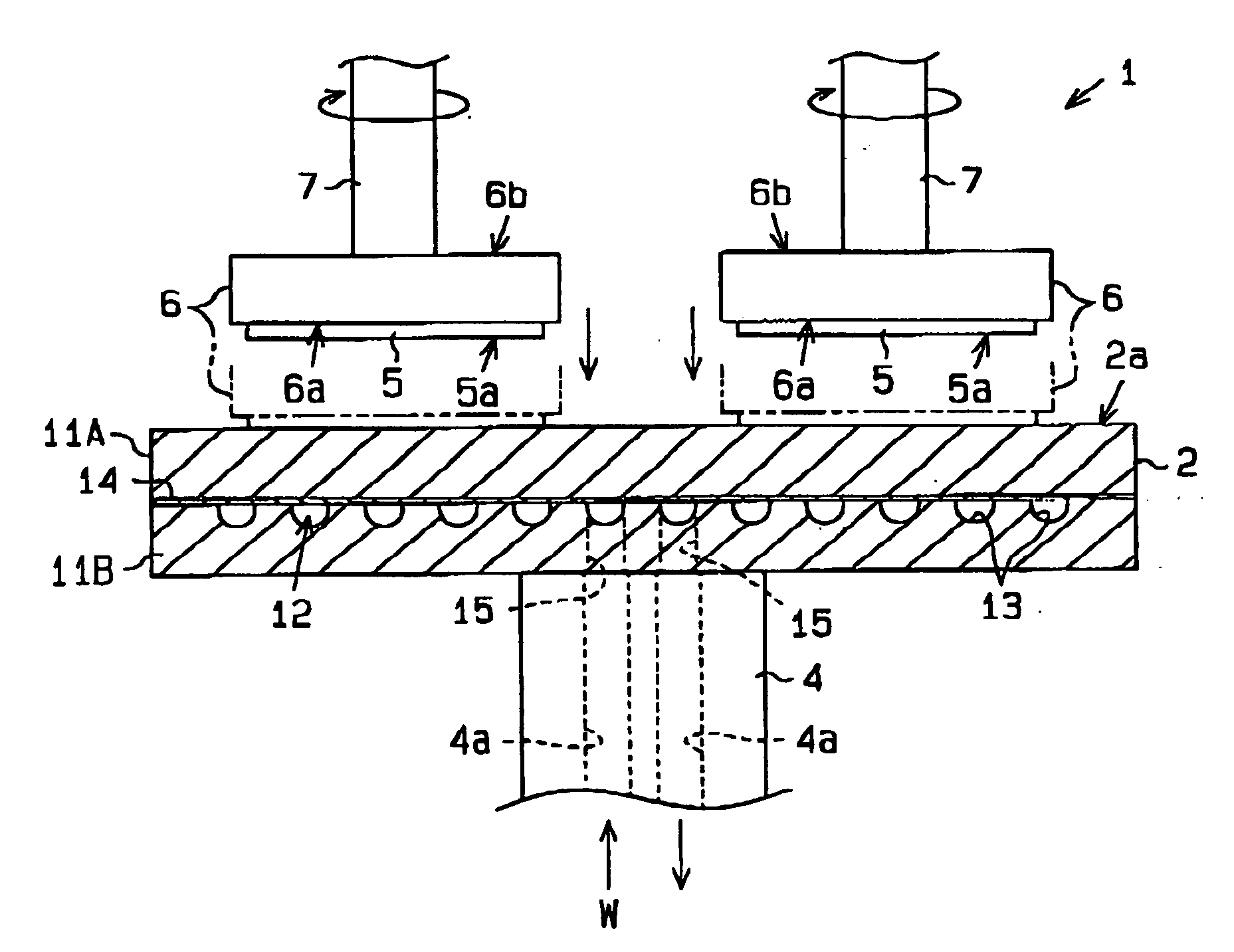
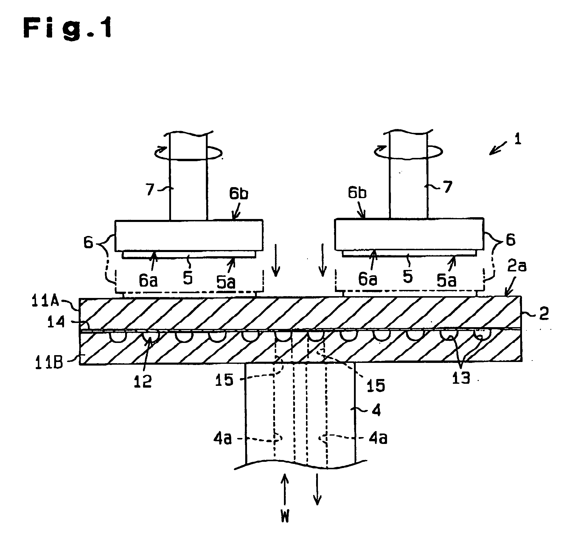
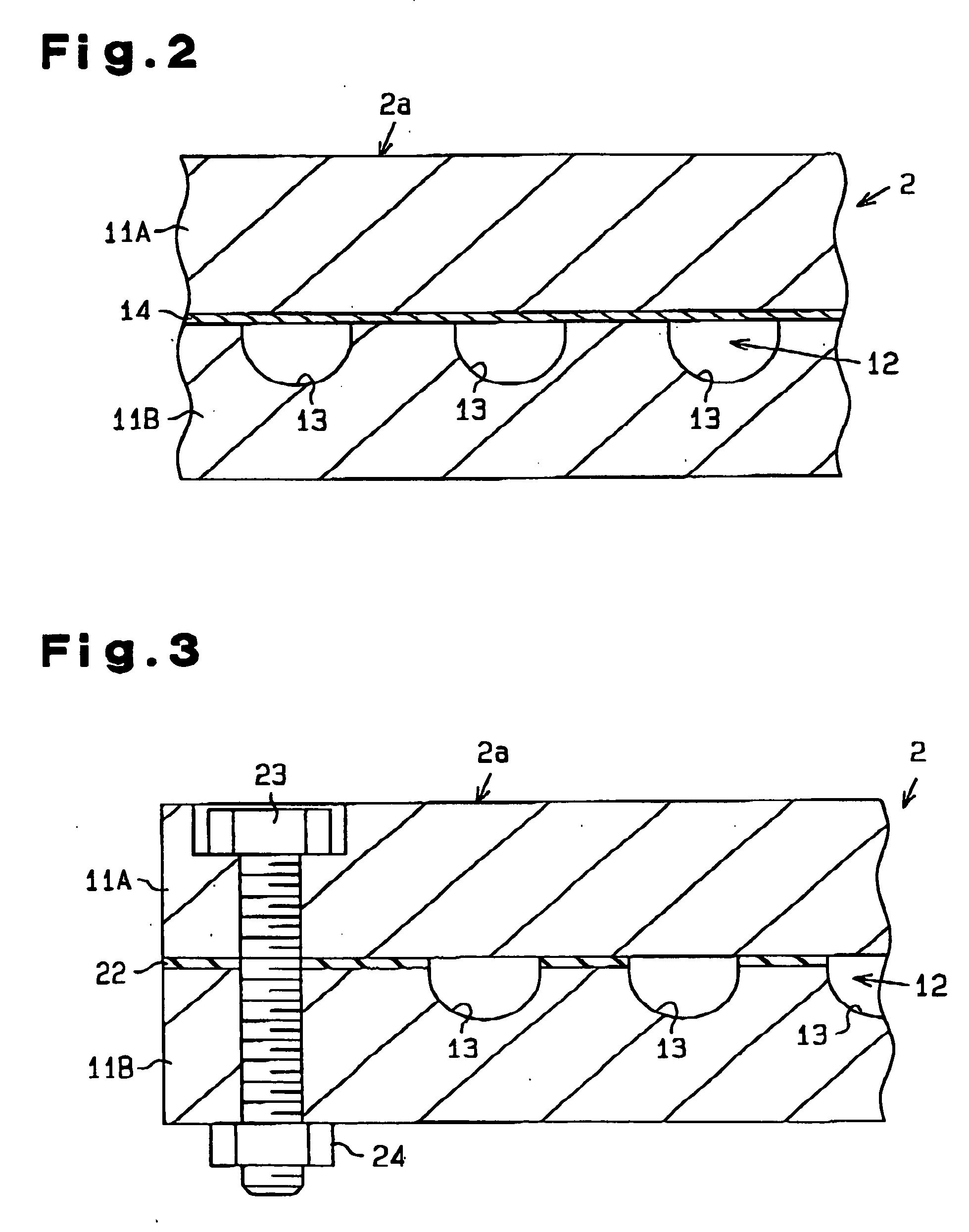
[0034] A wafer polishing apparatus 1 of the first embodiment will now be described in detail with reference to FIGS. 1 and 2. FIG. 1 schematically shows the wafer polishing apparatus 1 of the first embodiment. The wafer polishing apparatus 1 includes a disk-like table 2. A polishing surface 2a, on which a semiconductor wafer 5 is polished, is defined on the upper side of the table 2. A polishing cloth (not shown) is applied to the polishing surface 2a. In the first embodiment, a cooling jacket is not employed, and the table 2 is horizontally and directly secured to an upper end of a cylindrical rotary shaft 4. Thus, when the rotary shaft 4 is rotated, the table 2 rotates integrally with the rotary shaft 4.
[0035] As shown in FIG. 1, the wafer polishing apparatus 1 includes a plurality of wafer holding plates 6 (for the sake of brevity, only two are shown in FIG. 1). Each plate 6 is formed of, for example, glass, ceramic such as alumina, or metal such as stainless steel. A pusher rod...
referential example 1-1
[0050] In referential example 1-1, “beta random (trade name)”, product of IBIDEN KABUSHIKI KAISHA, was used as silicon carbide powder that contained 94.6 weight percent of β type crystals. The average crystal particle diameter of this powder was 1.3 micrometers. The powder contained 1.5 weight percent of boron and 3.6 weight percent of free carbon.
[0051] First, 5 weight parts of polyvinyl alcohol and 300 weight parts of water were added to 100 weight parts of the silicon carbide powder. The mixture was then stirred in a ball mill for five hours to obtain a uniform mixture. The mixture was dried for a predetermined time to remove a certain amount of moisture from the mixture. An appropriate amount of the dry mixture was then sampled and granulated. Next, the granules of the dry mixture were subjected to molding with metal press dies at a pressure of 50 kg / cm2. The density of the resulting molded body was 1.2 g / cm3.
[0052] Subsequently, the molded body was placed in a graphite crucib...
referential example 1-2
[0056] In referential example 1-2, α type silicon carbide powder (more specifically, “OY15 (trade name)”, product of YAKUSHIMA DENKO KABUSHIKI KAISHA) was employed in lieu of the β type. The density of each resulting base 11A, 11B was 3.1 g / cm3. The heat conductivity of each base 11A, 11B was 125 W / m·K. Each base 11A, 11B contained 0.4 weight percent of boron and 1.8 weight percent of free carbon. The heat conductivity of the bases 11A, 11B in referential example 1-1, in which the β type powder was the starting material, was approximately 20 percent higher than that of referential example 1-2.
[0057] After the table 2 was obtained through the same procedure as referential example 1-1, the table 2 was installed in the various types of apparatuses 1 to polish the semiconductor wafers 5 of different dimensions. Accordingly, substantially the same advantageous results as those of referential example 1-1 were obtained.
[0058] The first embodiment has the following advantages.
[0059] (1) ...
PUM
| Property | Measurement | Unit |
|---|---|---|
| Diameter | aaaaa | aaaaa |
| Electrical resistance | aaaaa | aaaaa |
| Adhesivity | aaaaa | aaaaa |
Abstract
Description
Claims
Application Information