Signal processor

a technology of signal processor and circuit components, applied in the direction of electrical control, machines/engines, instruments, etc., can solve the problems of affecting the effect of circuit component numeric value fluctuations and the inability to achieve the purpose of improvemen

Active Publication Date: 2005-11-24
MITSUBISHI ELECTRIC CORP
View PDF1 Cites 16 Cited by
  • Summary
  • Abstract
  • Description
  • Claims
  • Application Information

AI Technical Summary

Benefits of technology

[0011] An object of the present invention is to provide a signal processor capable of adjusting variab...

Problems solved by technology

This causes a problem in that the purpose of improvements is not achieved.
In the case where a more delicate adjustment is required, the influence of fluctuations in numeric value in circuit components will be a more serious drawback.
Therefore, in adjustin...

Method used


Image

  • Signal processor
  • Signal processor
  • Signal processor

Examples


first preferred embodiment

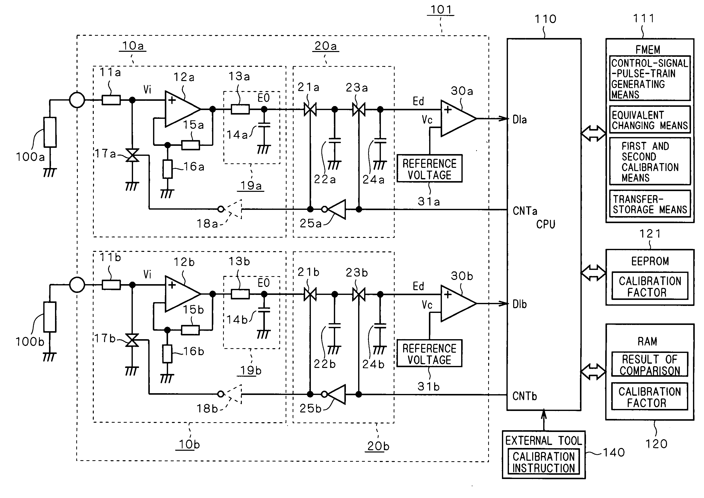
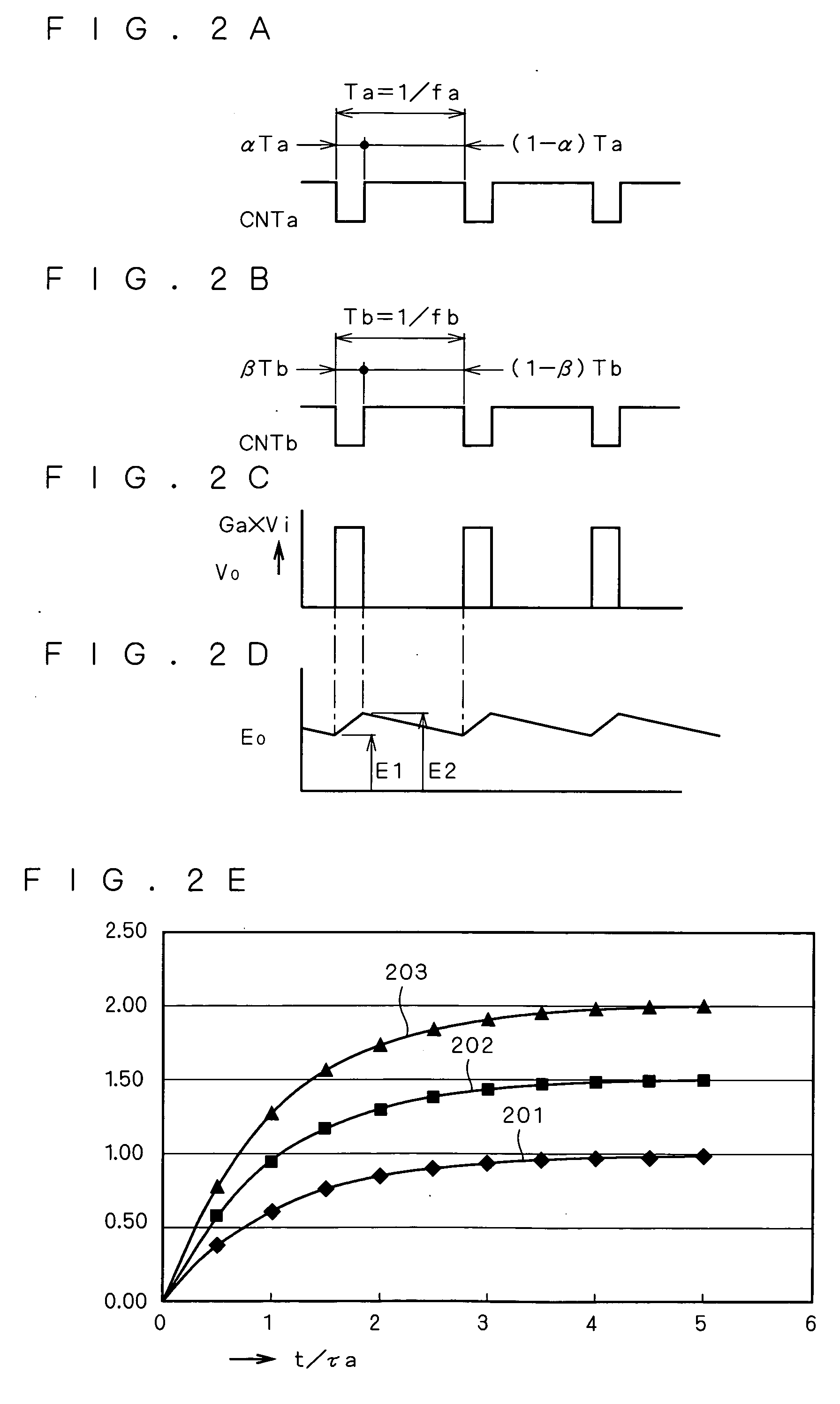
[0026]FIG. 1 is a circuit diagram of a signal processor according to the present embodiment. The following discussion is provided in reference to FIG. 1. An analog input signal processor 101 shown in FIG. 1 is provided between variable analog signal sources 100a, 100b and a microprocessor 110. The analog input signal processor 101 according to the present embodiment is formed by gain control circuits 10a, 10b, switched capacitor filter circuits 20a, 20b each constituting a low-pass filter circuit, and analog comparator circuits 30a, 30b serving as data converters. Output voltages of the analog signal sources 100a and 100b as input to the analog input signal processor 101 are compared with standard reference voltages 31a and 31b, respectively, and the results are input to the microprocessor 110 as digital logic signals DIa and DIb, respectively.

[0027] Now, the gain control circuit 10a will be described in detail. The gain control circuit 10a includes an amplifier 12a with an input r...

second preferred embodiment

[0070]FIG. 5 is a circuit diagram of a signal processor according to the present embodiment. In FIG. 5, an analog input signal processor 102 is provided between variable analog signal sources 100c, 100d and the microprocessor 110. The analog input signal processor 102 according to the present embodiment includes a gain control circuit 10c, a switched capacitor filter circuit 20c constituting a low-pass filter circuit, analog comparator circuits 30c, 30d serving as data converters and a multiplexer 40c. The results of comparisons between the analog signal source 100c and standard reference voltages 31c, 31d are input to the microprocessor 110 as digital logic signals DI1 and DI2, respectively, and are stored in the RAM memory 120.

[0071] The multiplexer 40c switches connection from the variable analog signal source 100c to the variable analog signal source 100d in response to a connection switching signal MPX generated by the microprocessor 110. With this switching, the comparisons a...

third preferred embodiment

[0080]FIG. 6 is a circuit diagram of a signal processor according to the present embodiment. The following discussion of the signal processor shown in FIG. 6 is focused on differences from that shown in FIG. 1. First, in the signal processor shown in FIG. 6, an analog input signal processor 103 is provided between the variable analog signal sources 100a, 100b and the microprocessor 110. The analog input signal processor 103 is formed by the gain control circuits 10a, 10b, switched capacitor filter circuits 20a, 20b each constituting a low-pass filter circuit and an AD converter 50 serving as a data converter. The signal voltages from the analog signal sources 100a and 100b are converted to digital form at the AD converter 50 and are input to the microprocessor 110.

[0081] The gain control circuits 10a, 10b and switched capacitor filter circuits 20a, 20b are the same as those shown in FIG. 1. However, the AD converter 50 is provided in place of the analog comparator circuits shown in...


PUM


Abstract

The present invention provides a signal processor including a microprocessor for generating and supplying a control signal pulse train, a gain control circuit having a first switching device opened/closed by the control signal pulse train and resistors for determining an amplification factor with respect to a signal voltage as input and varying the resistances of the resistors in response to a pulse duty of the control signal pulse train, thereby controlling the amplification factor with respect to the signal voltage as input, and a switched capacitor filter circuit having second switching devices opened/closed by the control signal pulse train and a charging/discharging capacitor connected to the second switching devices, thereby adjusting filter characteristics in response to the pulse frequency of the control signal pulse train. The control signal pulse train is supplied commonly to the first and second switching devices.

Description

BACKGROUND OF THE INVENTION [0001] 1. Field of the Invention [0002] The present invention relates to a signal processor, and more particularly to a signal processor for use in an internal combustion engine. [0003] 2. Description of the Background Art [0004] Among signal processors for use in internal combustion engines or the like, an analog input signal processor having the function of adjusting both the gain and frequency characteristics of the input signal processor has publicly been known, which is shown in, for example, Japanese Patent Application Laid-Open No. 2002-16460 (FIG. 1 and Abstract). JP 2002-16460 describes an invention related to a gain control circuit, and presents the concept of changing the switching duty ratio of switching devices connected in parallel or in series to a resistor that determines the gain of an operational amplifier, thereby adjusting the gain as well as controlling frequency characteristics of a filter in an alternating current amplifier. [0005] ...

Claims


Application Information

Patent Timeline
IPC IPC(8): F02D41/02G01L23/22F02D41/26F02D45/00G01L23/30G06G7/70H03G3/12H03H19/00
CPCF02D35/027F02D2041/1432F02D2041/1422F02D41/266
Inventor ABE, MINORUYAMASHITA, MANABU
Owner MITSUBISHI ELECTRIC CORP
Why Eureka
Try Eureka