
Laser noise cancel circuit and optical disk device

a noise reduction circuit and optical disk technology, applied in the field of laser noise reduction circuit and optical disk device, can solve the problems of difficult control, difficult to obtain a sufficient depression effect on laser noise, and adverse effects on reproduced signals, and achieve high noise reduction effect and high accuracy.

Inactive Publication Date: 2005-12-01
SONY CORP
View PDF5 Cites 4 Cited by
  • Summary
  • Abstract
  • Description
  • Claims
  • Application Information

AI Technical Summary

Benefits of technology

The present invention provides a laser noise cancel circuit and an optical disk device that can automatically and accurately adjust gains in amplifiers to cancel out laser noise. The circuit includes a gain-variable amplifying noise cancel circuit, low-pass filters, a negative return loop circuit, and an arithmetic circuit. The low-pass filters extract low-frequency signal components from a monitor output signal for noise canceling and a reproduced high-frequency signal from the optical disk. The negative return loop circuit controls the gain in the amplifying noise cancel circuit based on the low-frequency signal components of the monitor output signal for noise canceling and the low-frequency signal components of the reproduced high-frequency signal. The arithmetic circuit generates the reproduced high-frequency signal with the laser noise components canceled out. The invention achieves high noise reduction by adjusting gains in amplifiers in conjunction with laser noise cancellation.

Problems solved by technology

Conventional optical disk recorder and reproducing devices have the problem that laser noises may increase due to returned light from a disk or temperature change, and may have adverse effects on reproduced signals.
Since a noise level of a RF signal, likewise RF signals, depends on a reflection coefficient of a disk or other factors and varies depending on the conditions such as non-uniformity of disks to be reproduced or irregularities on a surface of each disk, in order to constantly obtain the maximized noise canceling effects, it has to be adjusted in such a way that laser noise levels emerging in the outputs of amplifiers 151 and 152 should be identical to each other, and therefore the control is difficult and it is not easy to obtain a sufficient depression effect on laser noises.

Method used


Image

  • Laser noise cancel circuit and optical disk device
  • Laser noise cancel circuit and optical disk device
  • Laser noise cancel circuit and optical disk device

Examples


first embodiment

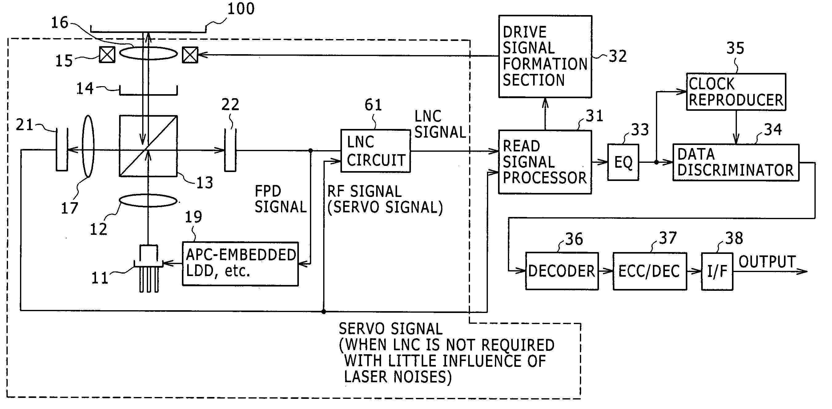
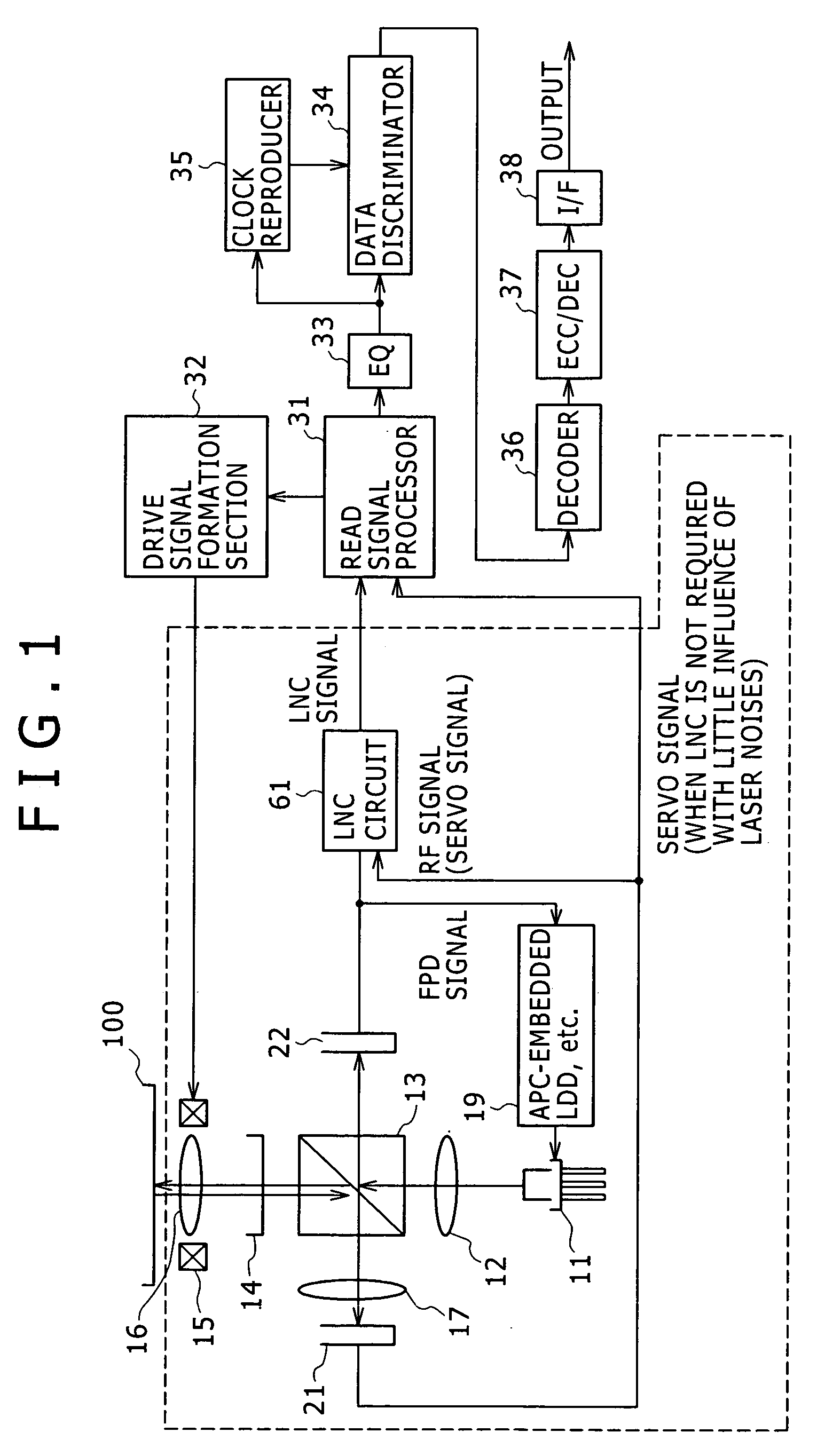
[0030]FIG. 1 is a block diagram explaining an optical disk device using a laser noise cancel circuit according to this first embodiment.

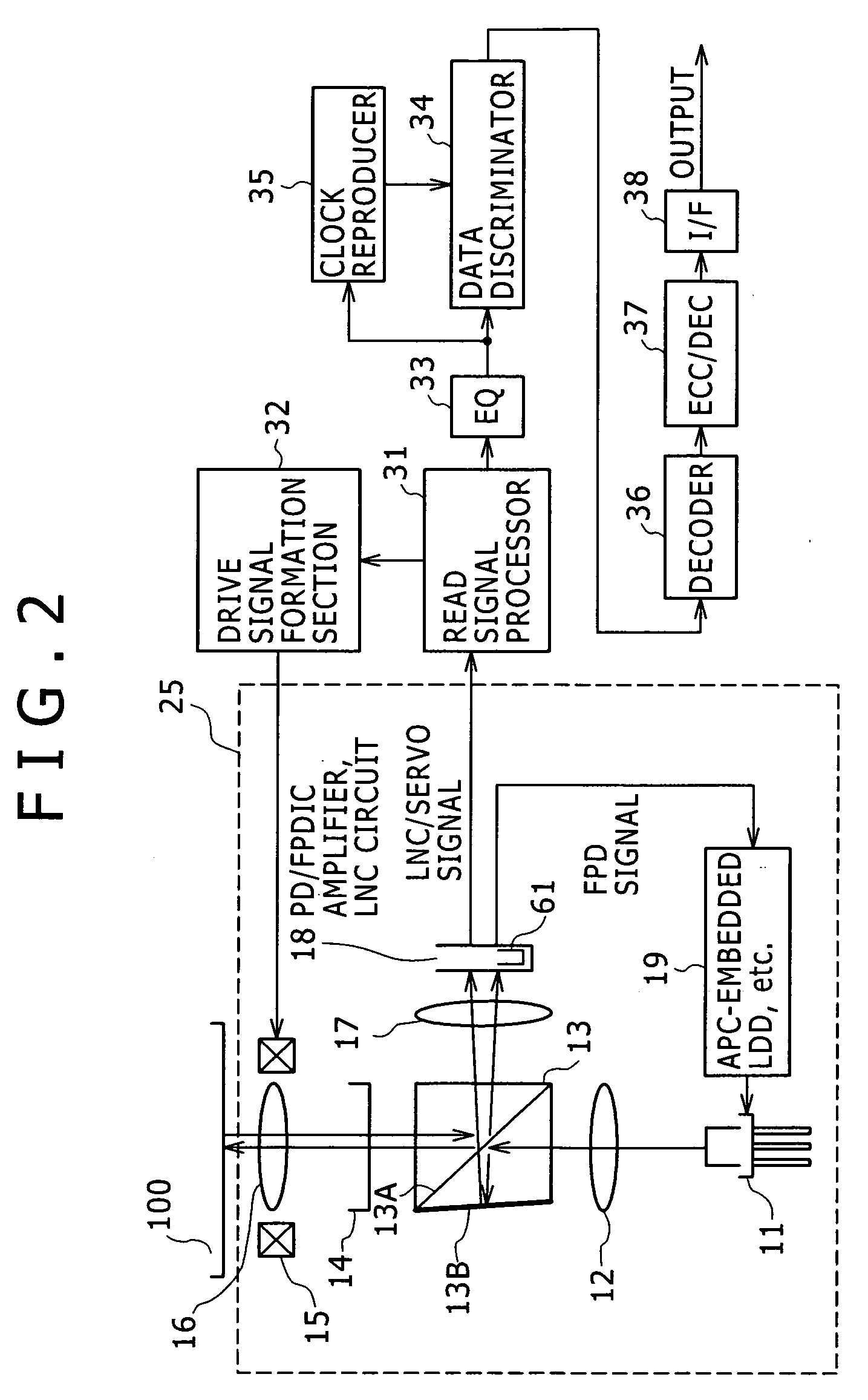
[0031] The optical disk device includes a light pickup section 1, a read signal processor 31, a drive signal formation section 32, an equalizer 33, a data discriminator 34, a clock reproducer 35, a decoder 36, an ECC (Error Correcting Code) decoder 37, and an interface section 38.

[0032] The light pickup section 1 includes a laser diode 11, a collimator lens 12, a polarizing splitter 13, a quarter wave plate 14, a coil system 15 for controlling focus, an objective lens 16, a condenser lens 17, an integrated element (hereinafter referred to as a PDIC) 21 embedding a main photodiode (hereinafter referred to as a main PD) and an amplifier, an integrated element (hereinafter referred to as a FPDIC) 22 embedding an front photodiode (hereinafter referred to as a front PD) and an amplifier, a laser noise cancel circuit 61, and a laser diode driving circui...

second embodiment

[0060]FIG. 4 is a circuit diagram showing a specific example of the laser noise cancel circuit 61 shown in FIG. 3. In FIG. 4, the same signs are assigned to the same circuit elements as those shown in FIG. 3 and descriptions are omitted herefrom.

[0061] In a laser noise cancel circuit 71 shown in FIG. 4, the amplifier 65 shown in FIG. 3 is replaced with a non-inverting amplifying circuit including a differential amplifier 520, resistors 521 and 522, and a MOS resistor (MOS resistor element) 523, so that application of the MOS resistor 523 as a return resistor leads a resistance value into variable, and by using the MOS resistor 523 as a return resistor, a resistance value of the MOS resistor 523 can be adjusted. Also by using a MOS resistor as a return resistor, the output from a differential amplifier 64 and a gain from the noninverting amplifying circuit is automatically adjusted, so as to determine a DC level of the output from the differential amplifier 520 to be identical to a ...

third embodiment

[0064]FIG. 5 is a circuit diagram showing another specific example of the laser noise cancel circuit 61 shown in FIG. 3.

[0065] In FIG. 5, the same signs are assigned to the same circuit elements as those shown in FIG. 3 and FIG. 4, and descriptions thereof are omitted herefrom.

[0066] In a laser noise cancel circuit 81 shown in FIG. 5 in the third embodiment, the amplifier 65 shown in FIG. 3 is replaced with a non-inverting amplifying circuit including a differential amplifier 520, resistors 521 and 533, and a MOS resistor (MOS resistor element) 532. Using a fixed resistor 533 as a return resistor for the differential amplifier 520, while inserting the MOS resistor 532 as a resistor between a reverse phase input terminal of the differential amplifier 520 and a reference voltage VREF, by adjusting a resistant value of this resistor 532 with the output from a differential amplifier 64, a gain from the noninverting amplifying circuit is automatically adjusted, so as to determine a DC ...


PUM

PropertyMeasurementUnit
frequencyaaaaaaaaaa
resistanceaaaaaaaaaa
resistance valueaaaaaaaaaa

Abstract

Disclosed herein is a laser noise cancel circuit for reducing laser noises in a reproduction system for an optical disk device including, a gain-variable amplifying noise cancel circuit for amplifying a monitor output signal for laser light, a first low-pass filter for extracting low frequency signal components of a monitor output signal for noise canceling, a second low-pass filter for extracting low frequency signal components, a negative return loop circuit for controlling a gain in the amplifying noise cancel circuit based on the low frequency signal components of the monitor output signal for noise canceling extracted as well as on the low frequency signal components of the reproduced high frequency signal extracted, to determine the low frequency signal component rate of the monitor output signal for noise canceling as identical to the low frequency signal component rate of the reproduced high frequency signal, and an arithmetic circuit for generating the reproduced high frequency signal with the laser noise components cancelled by canceling the laser noise components extracted from the monitor output signal for noise canceling with a low frequency signal component rate determined as identical to the low frequency signal component rate of the reproduced high frequency signal with the laser noise components of the reproduced high frequency signal.

Description

BACKGROUND OF THE INVENTION [0001] The present invention relates to a laser noise cancel circuit reducing laser noises arising from returned light from a disk or temperature change, and to an optical disk device using the laser noise cancel circuit. [0002] Conventional optical disk recorder and reproducing devices have the problem that laser noises may increase due to returned light from a disk or temperature change, and may have adverse effects on reproduced signals. There has been a method of reducing such laser noises, as already disclosed in Japanese Patent Laid-open No. Hei 10-124919, that is a laser noise cancel (LNC) system for canceling laser noises by subtracting laser light noise components monitored directly from light signals modulated by the disk. With the conventional technique using the subtraction method to obtain a high depression effect against laser noises, however, in the LNC arithmetic section, the level of a RF signal, which is a reproduced signal of data recor...

Claims


Application Information

Patent Timeline
Patent Type & Authority Applications(United States)
IPC IPC(8): G11B7/005G11B7/125G11B7/126G11B7/13G11B11/105G11B20/10G11B20/24
CPCG11B7/005G11B20/24G11B7/126A47J27/05A47J36/00A23L7/10A47J2027/043
Inventor FUKUTOMI, YOSHIONAGARA, TORU
Owner SONY CORP
Learn More