

Biocatalyst chamber encapsulation system for bioremediation and fermentation with improved rotor
a biocatalyst and encapsulation system technology, applied in biochemical apparatus and processes, specific use bioreactors/fermenters, after-treatment of biomass, etc., can solve the problems of high energy expenditure, low yield of product, and low rate of product formation, etc., to achieve high yield and increase the capacity of the device
- Summary
- Abstract
- Description
- Claims
- Application Information
AI Technical Summary
Benefits of technology
Problems solved by technology
Method used
Image

Examples
first embodiment
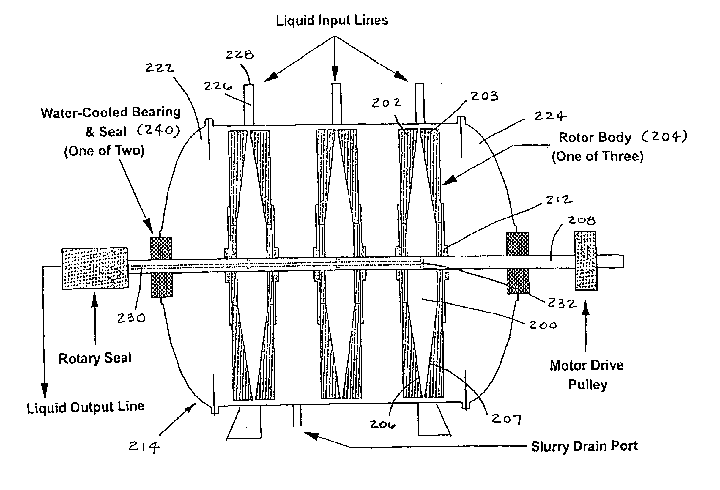
[0075]FIG. 10 depicts the components of the present invention. A cylindrical rotor body 20 is mounted on a horizontal, motor-driven rotating shaft 21 inside a safety containment chamber 22 bounded by metal walls. The rotor body 20 is fixed in position on the rotating shaft 21 by means of locking collars 23. The rotating shaft 21 is supported on either side of the rotor body 20 by bearings 24. The rotating shaft 21 extends outside the safety containment chamber 22 for a distance and ends in a terminal bearing and end cap 29 mounted in an external housing 25. Liquid flows are introduced into and removed from bioreactor chambers 26 mounted in the rotor body 20 by means of a liquid input mechanical end-face seal 28 and a liquid output mechanical end-face seal 27 which communicate with liquid channels (50, 51 in FIG. 22) within the rotating shaft 21. Typical dimensions for an example rotor body 20 (a=36 cm and b=15 cm) are entirely reasonable and comparable to rotor dimensions known to t...
second embodiment
[0081] To obtain data for an analysis of the performance of a rotor body (20 in FIG. 10) of the dimensions and configuration outlined in FIGS. 10-11 and 13-14 and containing demountable rectilinear biocatalyst immobilization chambers 43 like those depicted in FIG. 12, it was necessary that several scale dimensions and boundary equations be chosen arbitrarily and used to determine the operating characteristics of the invention. The immobilization boundary equations chosen are those listed in Equations 1 and 2 of FIG. 15 of U.S. Pat. No. 6,660,509.
[0082] In the embodiments of the present invention, described above, a portion of the geometry of the biocatalyst immobilization chamber (43 in FIG. 12) is that of a truncated cone. As is shown in FIG. 10, the dimensional problem of determining the “aspect ratio” (the ratio of the small radius of the truncated cone 110 to the large radius of the truncated cone) of the biocatalyst immobilization chamber (43 in FIG. 12) due to boundary conditi...
PUM
| Property | Measurement | Unit |
|---|---|---|
| flow rates | aaaaa | aaaaa |
| flow rates | aaaaa | aaaaa |
| flow rates | aaaaa | aaaaa |
Abstract
Description
Claims
Application Information