Method for producing poly(methyl methacrylate)-metal cluster composite

Inactive Publication Date: 2005-12-01
NAT INST OF ADVANCED IND SCI & TECH
View PDF2 Cites 1 Cited by
  • Summary
  • Abstract
  • Description
  • Claims
  • Application Information

AI Technical Summary

Benefits of technology

[0007] As a result of extensive studies on a process for producing a poly(methyl methacrylate)-metal cluster composite, the present inventors have found that poly(methyl methacrylate) changes in structure upon ultraviolet irradiation to remarkably increase the reduci

Problems solved by technology

However, since it involves many difficulties to uniformly disperse fine heavy metal particles in a matrix material, various devices are necessary for overcoming the problems.
Thus, some proposals have hitherto been performed, but there are problems that all these methods contain diversified steps and operations thereof are complicated.
However, poly(methyl methacrylate) has, unlike other polymer compounds, weak reducing power toward heavy metal compounds and hence it is very difficult to obtain metal cluster complexes thereof (cf.

Method used


Image

  • Method for producing poly(methyl methacrylate)-metal cluster composite
  • Method for producing poly(methyl methacrylate)-metal cluster composite
  • Method for producing poly(methyl methacrylate)-metal cluster composite

Examples


example 1

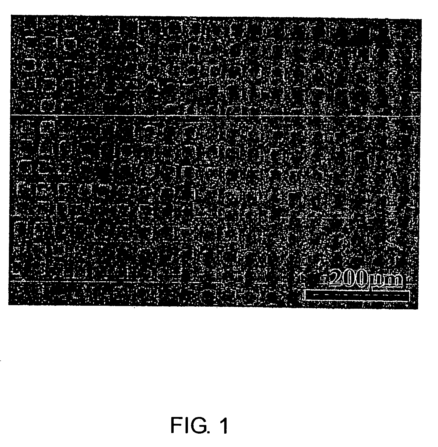
[0042] A poly(methyl methacrylate) (PMMA) film on which a metal mesh having a large number of holes of 5-μm-square had been placed as a mask was irradiated with ultraviolet ray (containing wavelength of 250 nm to 350 nm) of 1.9 J / cm2 by means of a mercury lamp. After removal of the mask, the film and palladium(II) acetylacetonate were placed in a glass tube and, under a nitrogen atmosphere, the glass tube was immersed in an oil bath at 180° C. for 15 minutes. The palladium(II) acetylacetonate sublimed and diffused inside the PMMA film. Since the portion exposed to ultraviolet ray strongly reduced the metal complex, a pattern of metal nanoparticles was obtained in accordance with the pattern of the metal mesh used as the mask. When the film was observed by a back scattering mode on a scanning electron microscope (SEM), the portion where the metal was formed strongly scattered an electron beam and hence afforded a bright contrast, so that it was confirmed that the pattern of the photo...

example 2

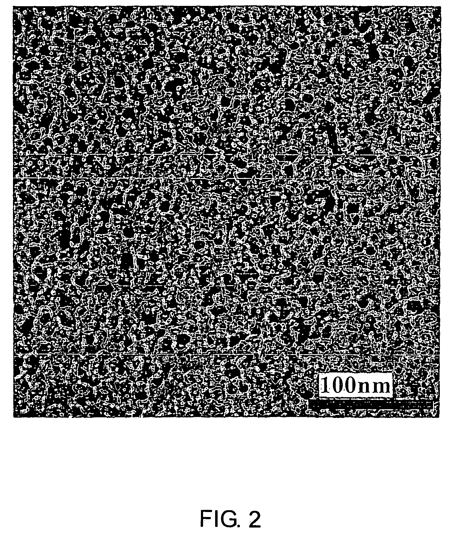
[0044] When vapor of cobalt(II) acetylacetonate and the PMMA film were placed under a nitrogen atmosphere at 180° C. for 30 minutes in the same manner as in Example 1, except that palladium(II) acetylacetonate was replaced with the cobalt complex, a micropattern of cobalt fine particles was obtained as in the case of palladium. It was confirmed by TEM observation that a large number of cobalt fine particles having a diameter of about 10 nm were dispersed in PMMA irradiated with the light.

example 3

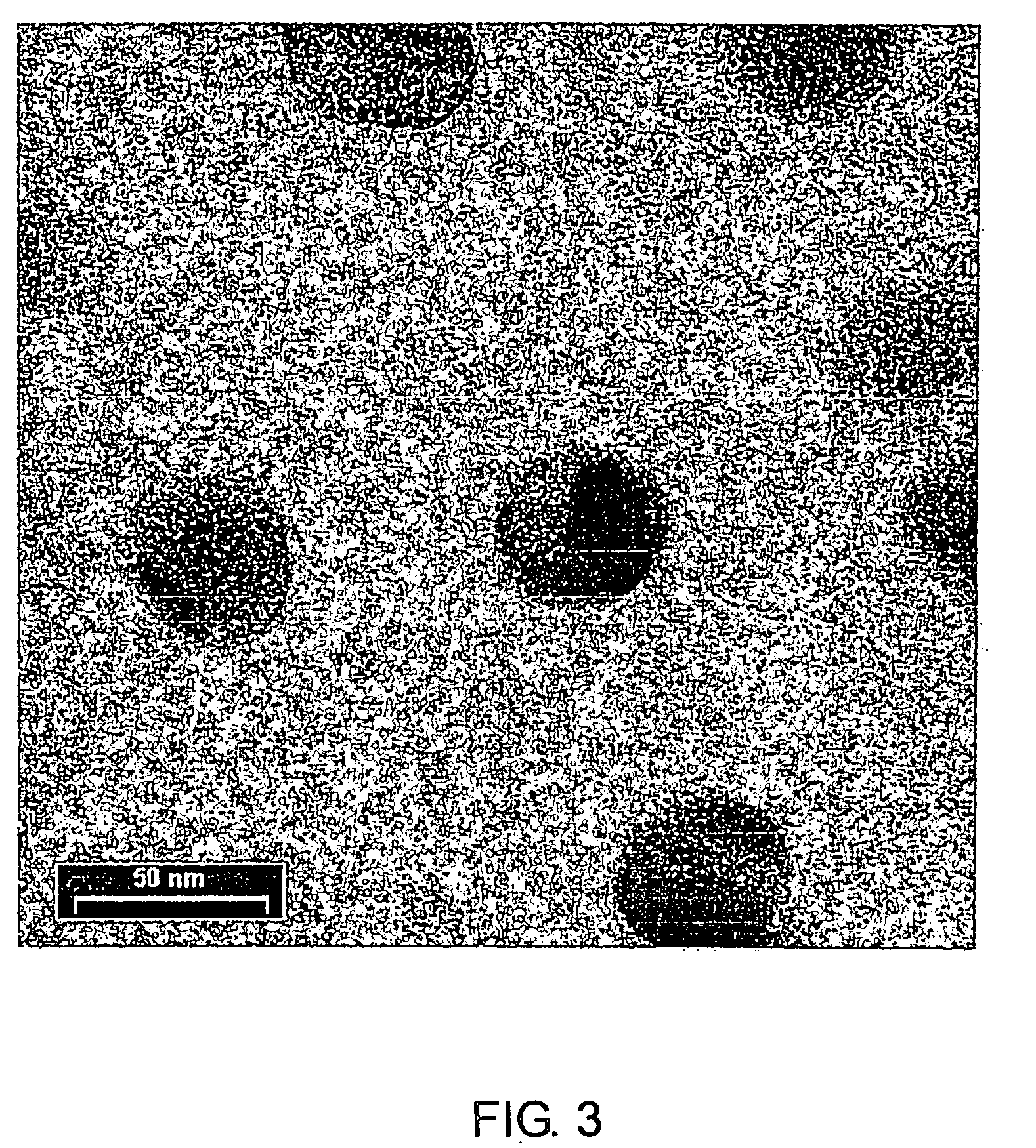
[0045] When vapor of copper(II) acetylacetonate and the PMMA film were placed under a nitrogen atmosphere at 180° C. for 30 minutes in the same manner as in Example 1, except that palladium(II) acetylacetonate was replaced with the copper complex, a micropattern of copper fine particles was obtained as in the case of palladium. It was confirmed by TEM observation that a large number of cobalt fine particles having a diameter of about 50 nm were dispersed in PMMA irradiated with the light (FIG. 3).


PUM

PropertyMeasurementUnit
Temperatureaaaaaaaaaa
Glass transition temperatureaaaaaaaaaa

Abstract

A process for efficiently producing a poly(methyl methacrylate)-metal cluster composite, a patterning material obtainable by the process, and its patterning method are provided. The poly(methyl methacrylate)-metal cluster composite is obtained by bringing a poly(methyl methacrylate) base plate having an ultraviolet-irradiated portion into contact with vapor of a heavy metal compound to form heavy metal nanoparticles on the ultraviolet-irradiated portion.

Description

TECHNICAL FIELD [0001] The present invention relates to a novel process for producing a poly(methyl methacrylate)-metal cluster composite which is expected to be useful as optical materials, electronic materials, and the like. More specifically, the present invention relates to a process for efficiently producing a poly(methyl methacrylate)-metal cluster composite using poly(methyl methacrylate) and a heavy metal complex as raw materials, and a patterning material obtained by the process. BACKGROUND ART [0002] A composite in which a polymer compound is used as a matrix and a heavy metal is dispersed therein in a fine state, i.e., so-called a polymer-metal cluster composite, has a non-linear optical property and a high elastic modulus property or is colored stably, so that the complex has attracted attention as non-linear optical materials, high elastic modulus materials, decorative materials, and the like. However, since it involves many difficulties to uniformly disperse fine heavy...

Claims


Application Information

Patent Timeline
IPC IPC(8): C08J7/00B22F9/20C08J7/06C23C16/04C23C16/44
CPCC08J7/06C23C16/047C08J2333/12C08L33/12C08K3/10C08K2201/011
Inventor HORIUCHI, SHIN
Owner NAT INST OF ADVANCED IND SCI & TECH
Why Eureka
Try Eureka