Noninvasive analyzer sample probe interface method and apparatus

a sample probe and analyzer technology, applied in the field of noninvasive sampling, can solve the problems of inefficient collection of diffusely reflected light, diabetes is a leading cause of death and disability worldwide, and the production and use of insulin are abnormal

Active Publication Date: 2005-12-01
GLT ACQUISITION
View PDF89 Cites 35 Cited by
  • Summary
  • Abstract
  • Description
  • Claims
  • Application Information

AI Technical Summary

Benefits of technology

[0002] The invention relates to noninvasive sampling. More particularly, the invention relates to a sample probe interface method and apparatus for use in conjunction with an optically based noninvasive analyzer. More particularly, the invention relates to a dynamic probe interface, wherein at least part of a sample probe moves in a controlled fashion relative to a tissue sample to control spectral variations resulting from the sample probe displacement of the tissue sample during a sampling process.

Problems solved by technology

Diabetes is a chronic disease that results in abnormal production and use of insulin, a hormone that facilitates glucose uptake into cells.
Diabetes is a leading cause of death and disability worldwide.
A disadvantage of this system is that it does not efficiently collect diffusely reflected light and the alignment is problematic.
In addition, spectra are not collected during a period of relative motion between the sample and the analyzer.
To date, no FDA device has been approved for use by an individual or a medical professional for noninvasive glucose concentration estimation.
Further, current reported versions of noninvasive glucose concentration analyzers do not consistently yield accurate estimations of glucose concentrations in patient trials.
A key source of error in the glucose concentration estimation is related to the probe design and patient interface, as opposed to the spectrograph unit or algorithm design.

Method used


Image

  • Noninvasive analyzer sample probe interface method and apparatus
  • Noninvasive analyzer sample probe interface method and apparatus
  • Noninvasive analyzer sample probe interface method and apparatus

Examples


first example embodiment

THE INVENTION

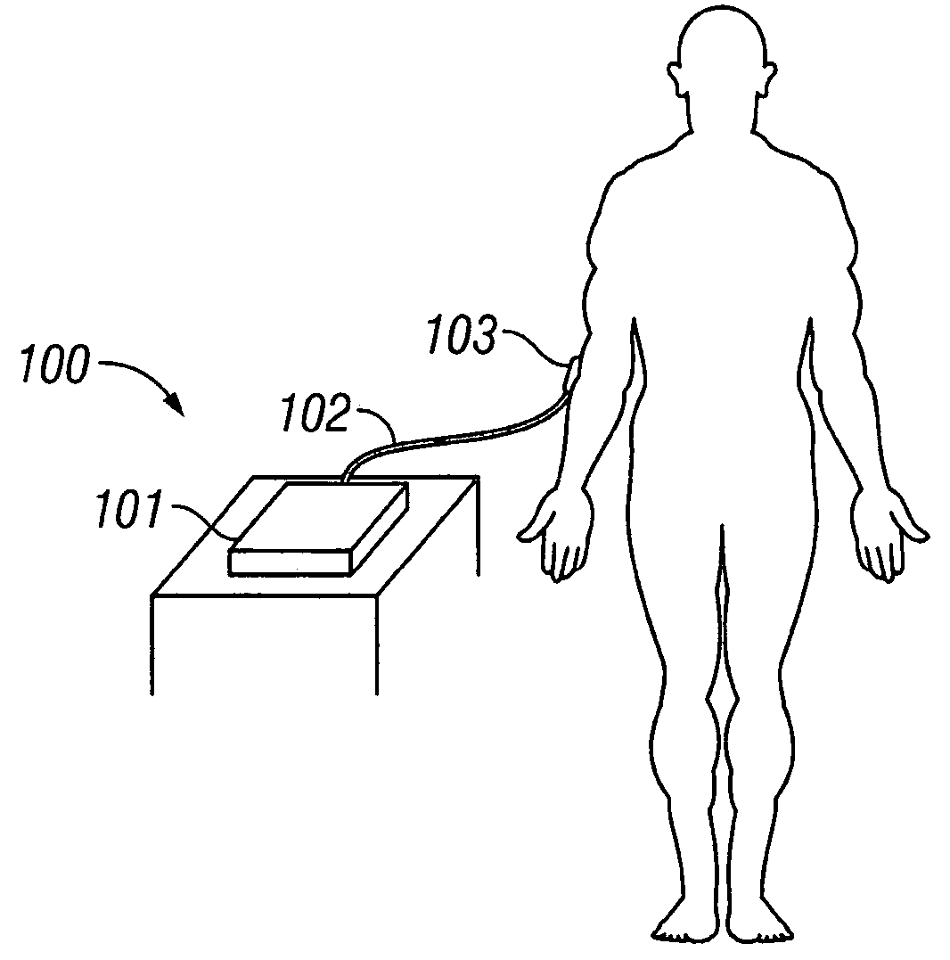
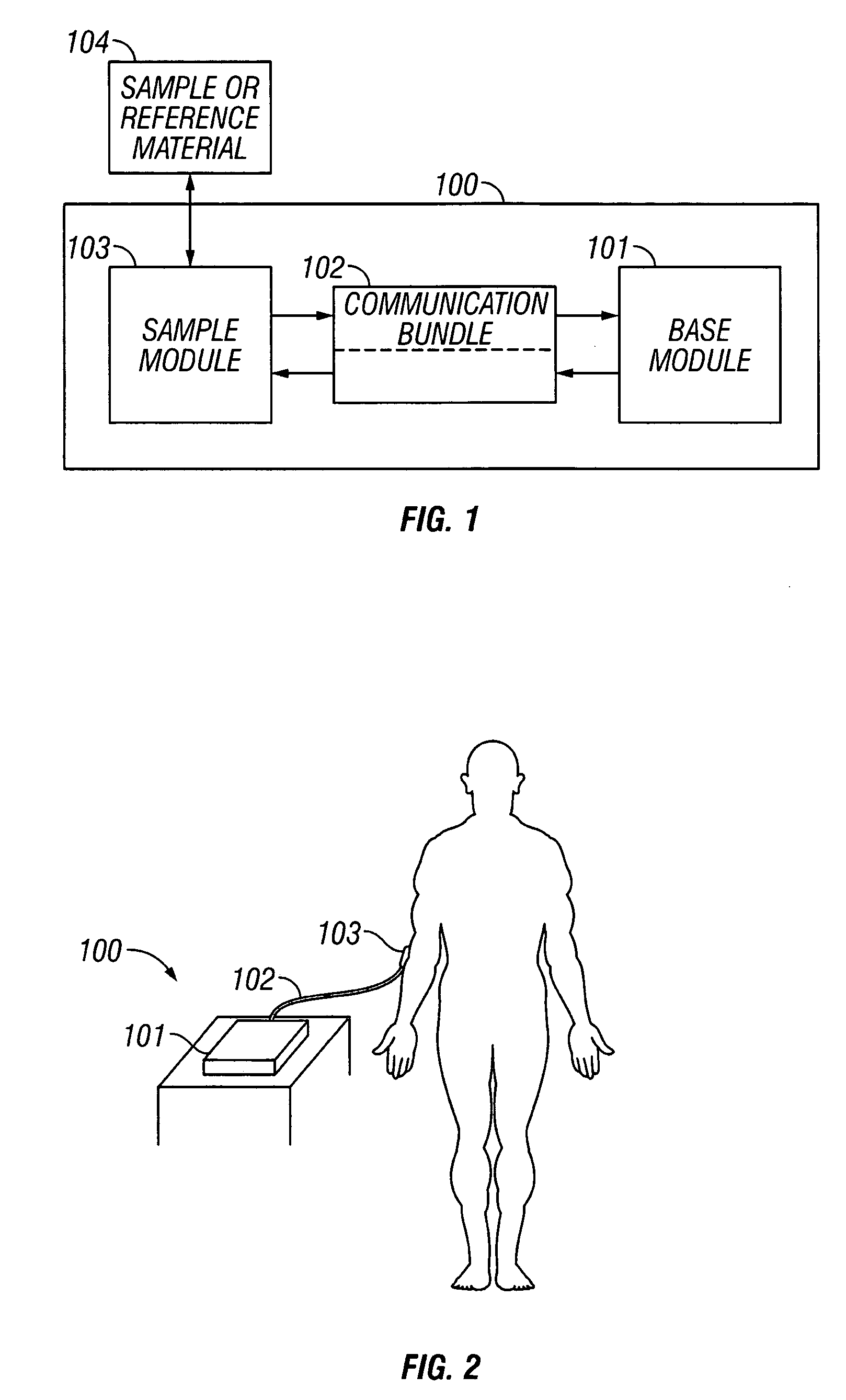
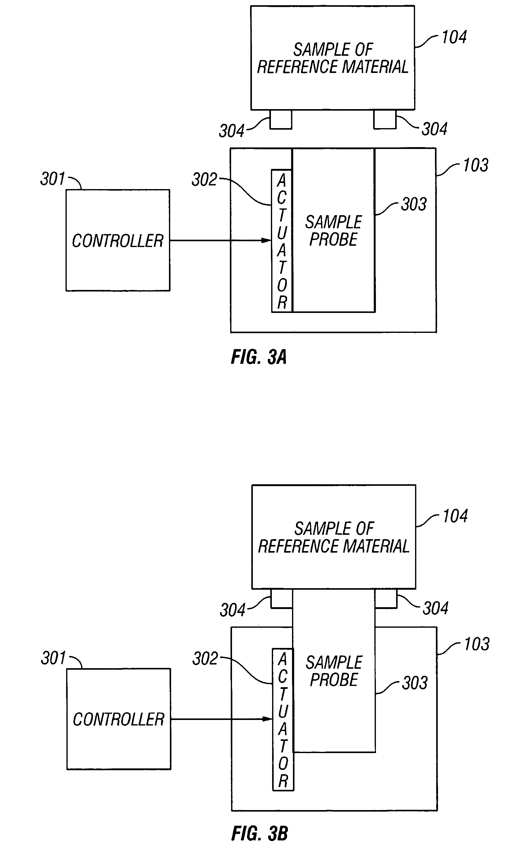
[0095] In a first embodiment of the invention, the sample probe 303 is a part of the sample module 103 and the sample probe is controlled roughly along at least the z-axis, which is an axis perpendicular to the x,y plane defined by a tangential plane to the sample site.

[0096] In this first embodiment, given species types of the base module genus, sample module genus, and communication bundle genus are used. Therefore, reference numbering of the base module species, sample module species, and communication bundle species in this example are given distinct numbers from the genus.

Tissue Sample

[0097] In the first embodiment of the invention, the analyte concentration is determined using a sample site on the back of the forearm. However, other regions or volumes of the body subjected to noninvasive measurements include: a hand, finger, palmar region, base of thumb, forearm, volar aspect of the forearm, dorsal aspect of the forearm, upper arm, head, earlobe, eye, tongue, ...


PUM

PropertyMeasurementUnit
movement velocityaaaaaaaaaa
wavelengthaaaaaaaaaa
radial distancesaaaaaaaaaa

Abstract

A method and apparatus are provided for noninvasive sampling. More particularly, the method and apparatus relate to control of motion of an optical sample probe interface relative to a tissue sample site. A dynamic probe interface, is used to collect spectra of a targeted sample, control positioning of the sample probe relative to the tissue sample in terms of at least one of x-, y-, and z-axes, and/or control of sample tissue displacement to minimize spectral variations resulting from the sampling process and increase analyte property estimation precision and accuracy.

Description

BACKGROUND OF THE INVENTION [0001] 1. Field of the Invention [0002] The invention relates to noninvasive sampling. More particularly, the invention relates to a sample probe interface method and apparatus for use in conjunction with an optically based noninvasive analyzer. More particularly, the invention relates to a dynamic probe interface, wherein at least part of a sample probe moves in a controlled fashion relative to a tissue sample to control spectral variations resulting from the sample probe displacement of the tissue sample during a sampling process. [0003] 2. Description of Related Art [0004] Spectroscopy based noninvasive analyzers deliver external energy in the form of light to a specific sampling site, region, or volume of the human body where the photons interact with a tissue sample, thus probing chemical and physical features. A number of incident photons are specularly reflected, diffusely reflected, scattered, or transmitted out of the body where they are detected...

Claims


Application Information

Patent Timeline
Patent Type & Authority Applications(United States)
IPC IPC(8): A61B5/00G01N21/35
CPCA61B5/14532A61B5/1455A61B5/1495G01N21/359A61B2560/0223A61B2560/0233A61B2562/0242A61B5/4869
Inventor BLANK, THOMAS B.ACOSTA, GEORGE M.RUCHTI, TIMOTHY L.MATTU, MUTUALORENZ, ALEXANDER D.HAZEN, KEVIN H.HENDERSON, JAMES R.
Owner GLT ACQUISITION
Why Eureka
Try Eureka