Vehicle operation assisting system

US20050267683A1Inactive Publication Date: 2005-12-01HONDA MOTOR CO LTD

Image

  • Vehicle operation assisting system
  • Vehicle operation assisting system
  • Vehicle operation assisting system

Examples


Embodiment Construction

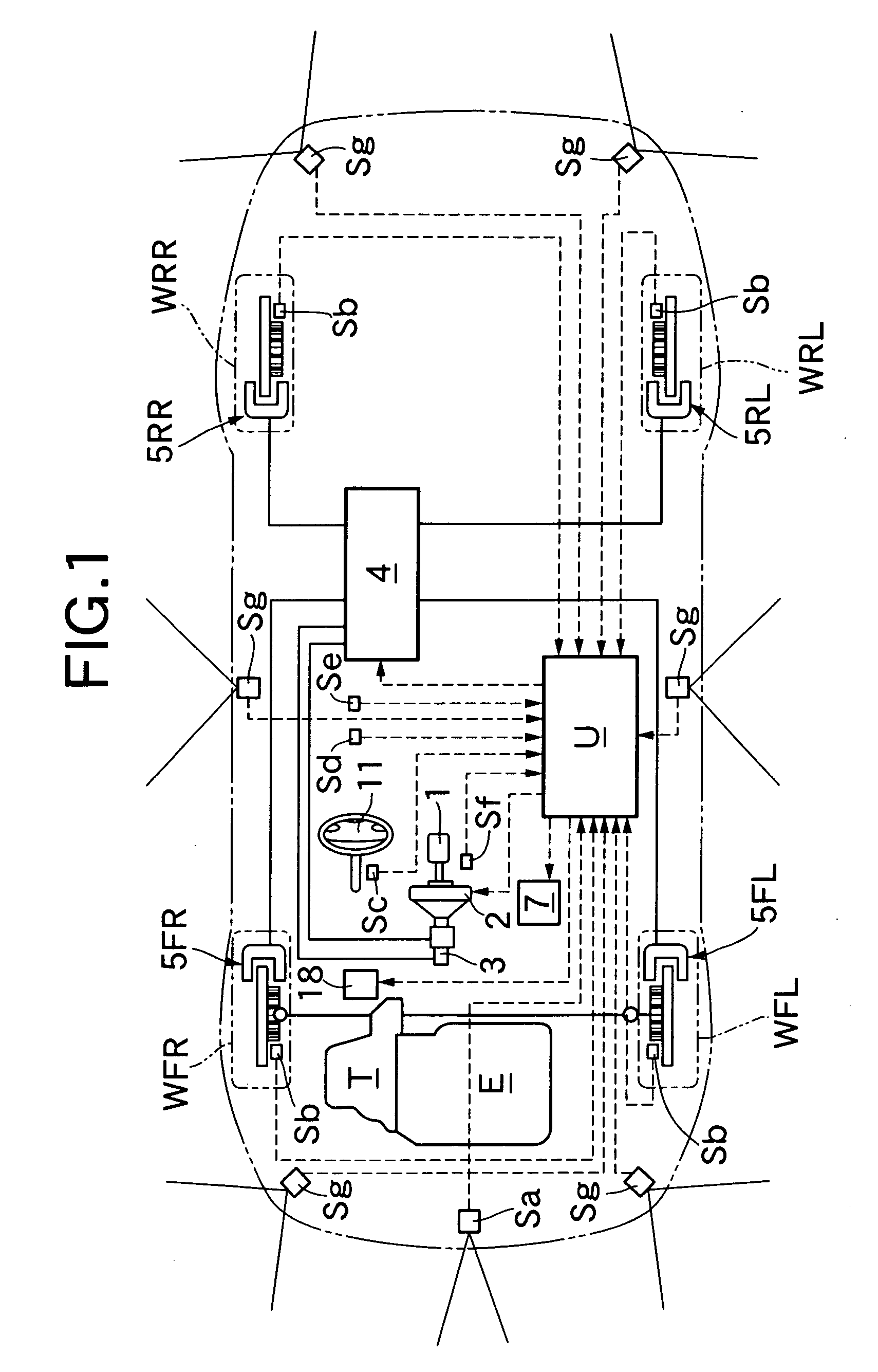
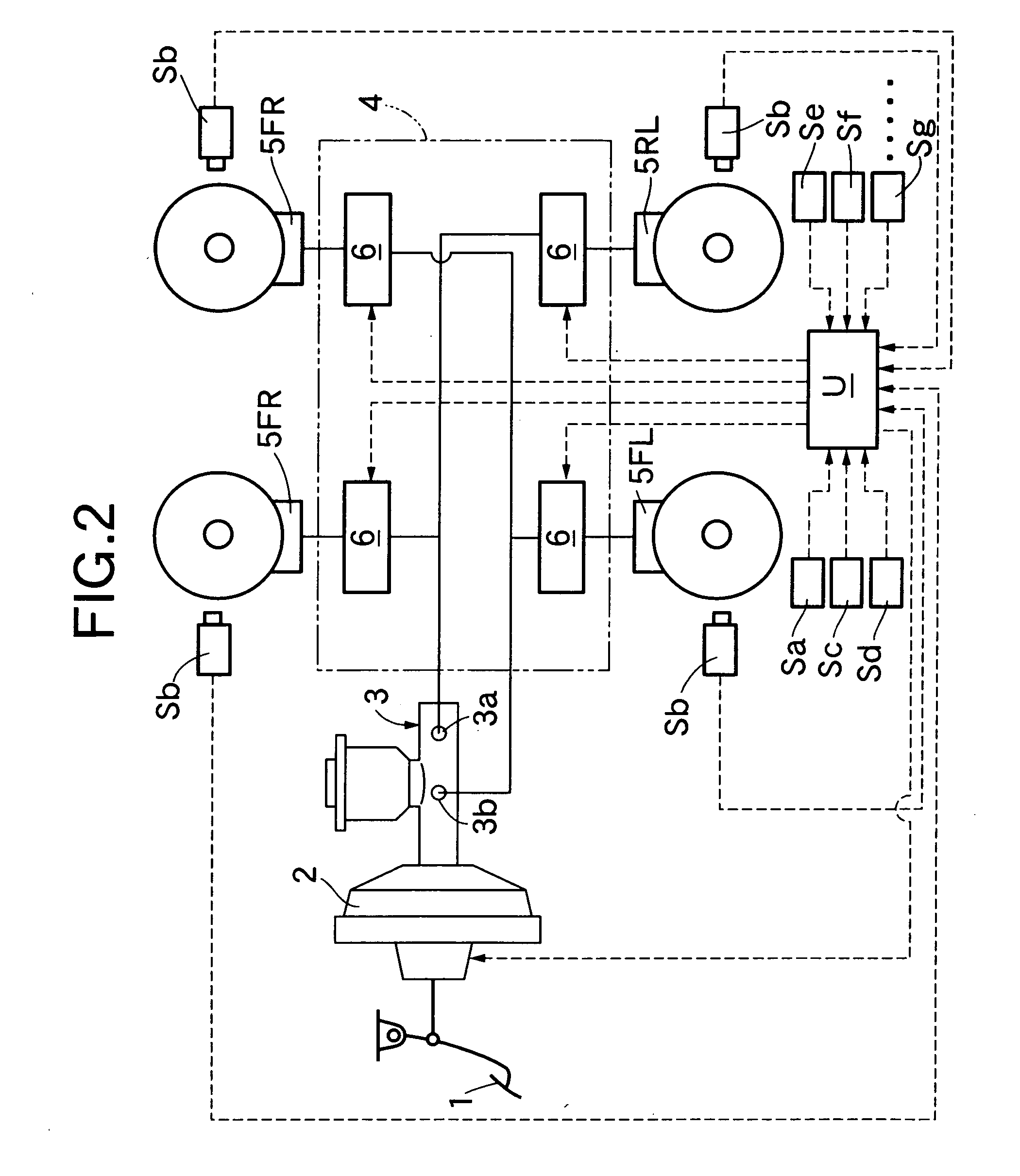
[0022] As shown in FIGS. 1 and 2, a four-wheel vehicle mounting an operation assisting system of this embodiment includes left and right front wheels WFL and WFR as driven wheels to which a driving force of an engine E is transmitted via a transmission T, and left and right rear wheels WRL and WRR as follower wheels rotating with traveling of the vehicle. A brake pedal 1 operated by a driver is connected to a master cylinder 3 via an electronic control negative pressure booster 2 constructing a part of the braking device of the present invention. The electronic control negative pressure booster 2 operates the master cylinder 3 by mechanically boosting the pressing force applied to the brake pedal 1, and operates the master cylinder 3 by a braking command signal from an electronic control unit U without the operation of the brake pedal 1 at the time of automatic braking. When a pressing force is inputted onto the brake pedal 1, and the braking command signal is inputted from the elec...


PUM


Abstract

A vehicle operation assisting system includes an assist yaw rate calculator which calculates an assist yaw rate necessary to avoid an obstacle based on a detection result of the obstacle by a radar device, an actual vehicle moving amount calculator which calculates an actual vehicle moving amount from a yaw rate and a lateral acceleration of a vehicle. When an avoiding operation detector determines an avoiding operation of a driver, a target vehicle moving amount setting device replaces a standard moving amount based on an avoiding operation of a driver with the assist yaw rate, and a vehicle movement controller controls lateral movement of the vehicle so that the actual vehicle moving amount agrees with the assist yaw rate. At this time, in addition to the yaw rate, the lateral acceleration is also used for calculating the actual vehicle moving amount, and therefore an upset of the vehicle behavior can be avoided by properly controlling the lateral movement of the vehicle on a road having a low friction coefficient on which the tires easily skid. A vehicle operation assisting system capable of properly performing an obstacle avoiding operation and a restoring operation even on a road having a low friction coefficient is thereby provided.

Description

RELATED APPLICATION DATA [0001] Japanese priority application No. 2004-145304, upon which the present application is based, is hereby incorporated in its entirety herein by reference. BACKGROUND OF THE INVENTION [0002] 1. Field of the Invention [0003] The present invention relates to a vehicle operation assisting system for assisting an obstacle avoiding operation of a vehicle and a restoring operation following the avoiding operation. [0004] 2. Description of the Related Art [0005] Japanese Patent Application Laid-open No. 7-21500 discloses an automatic brake control system which determines the possibility of the subject vehicle on which the system is installed colliding with an obstacle based on a distance between the subject vehicle and the obstacle and a relative speed detected by the radar device; and automatically actuates a brake device of the vehicle when the possibility of collision is confirmed. In this system, when it is determined that collision with the obstacle cannot ...

Claims


Application Information

Patent Timeline
01 Dec 2005
Publication
US20050267683A1
IPC
B60R21/00; B60T7/12; B60T8/1755; B60T8/58; B60W30/00; B60W30/09; B62D15/02; G01S1/00; G01S13/931; G08G1/16
CPC
B60T8/17558; B60T2201/022; B60W2550/20; B62D15/026; G01S2013/9353; G01S2013/9367; G01S2013/9342; G01S2013/9346
Inventors
FUJIWARA, YUKIHIRO; KANABOSHI, MITSUHARU