Fast start-up combined cycle power plant

a combined cycle and power plant technology, applied in the direction of machines/engines, steam generation using hot heat carriers, lighting and heating apparatus, etc., can solve the problems of affecting the efficiency of the power plant, so as to achieve the effect of effectively preventing the vibration of the damper

Inactive Publication Date: 2005-12-08
THE TOKYO ELECTRIC POWER CO INC +1
View PDF5 Cites 74 Cited by
  • Summary
  • Abstract
  • Description
  • Claims
  • Application Information

AI Technical Summary

Benefits of technology

[0018] In this configuration, by closing all dampers, the exhaust gas becomes not to be introduced into the heat recovery steam generator, and a drastic heat input does not act on the heat recovery steam generator. In addition, by selectively opening a damper, an introduction amount of the exhaust gas introduced into the heat recovery steam generator can be adjusted. Also in this case, because the damper is supported by the exhaust gas duct, a vibration of the damper can be effectively prevented.

Problems solved by technology

But if starting up the combined cycle power plant and directly introducing an exhaust gas of a high temperature exhausted from the gas turbine into the heat recovery steam generator, for example, there is such a possibility that strains occur in pipes configuring the heat recovery steam generator and the pipes break, due to a drastic heat input by the exhaust gas.
Therefore, in order to prevent the breakage of the heat recovery steam generator, although a method of controlling an output of the gas turbine while suppressing the output is adopted, there is a problem in the method that it takes very long time, by which the output of the gas turbine is raised to a rated load thereof and power is taken out.
But in suggestions of providing a damper described in the patent documents 1 to 3, because an exhaust gas of a very high pressure is blown into the damper, there is a possibility that only if the damper is simply supported, it fiercely vibrates due to a wind pressure, a strong force acts on such a damper drive for supporting the damper, and thus is damaged.
In addition, by a vibration occurring in a damper, it becomes unable to highly accurately control an introduction amount introduced into a heat recovery steam generator and a bypass amount of an exhaust gas bypassing the heat recovery steam generator: there is also a possibility that a drastic heat input is produced for the heat recovery steam generator, and that the heat recovery steam generator is damaged.
Furthermore, as a conventional heat recovery steam generator, although a natural circulation type is adopted, it has a drum of a very large thickness: an excessive thermal stress occurs due to a drastic heat inflow; it is necessary to suppress a load up rate in an operation of a damper; and as a result there is such a problem that a start-up time becomes longer.

Method used


Image

  • Fast start-up combined cycle power plant
  • Fast start-up combined cycle power plant
  • Fast start-up combined cycle power plant

Examples


first embodiment

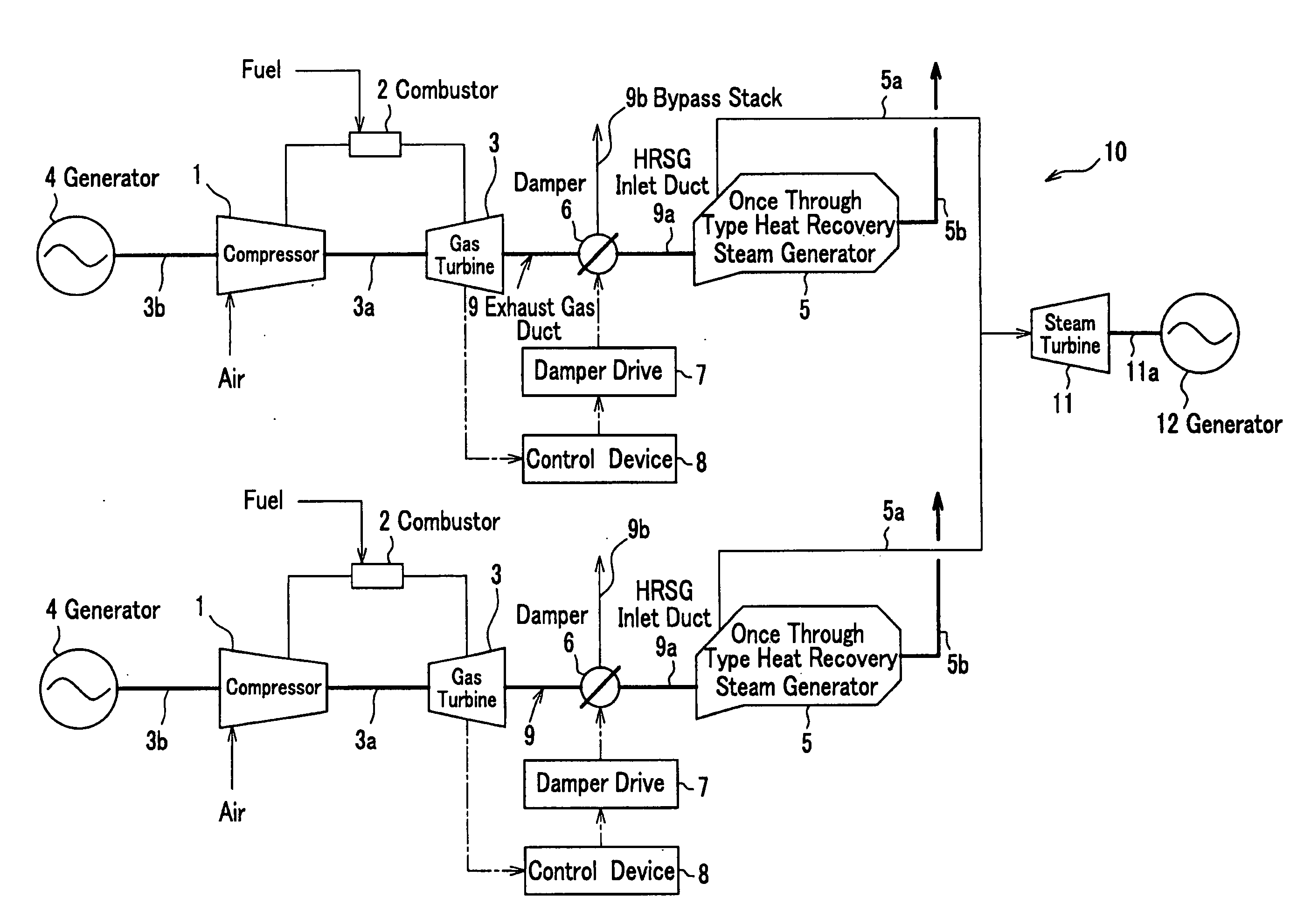
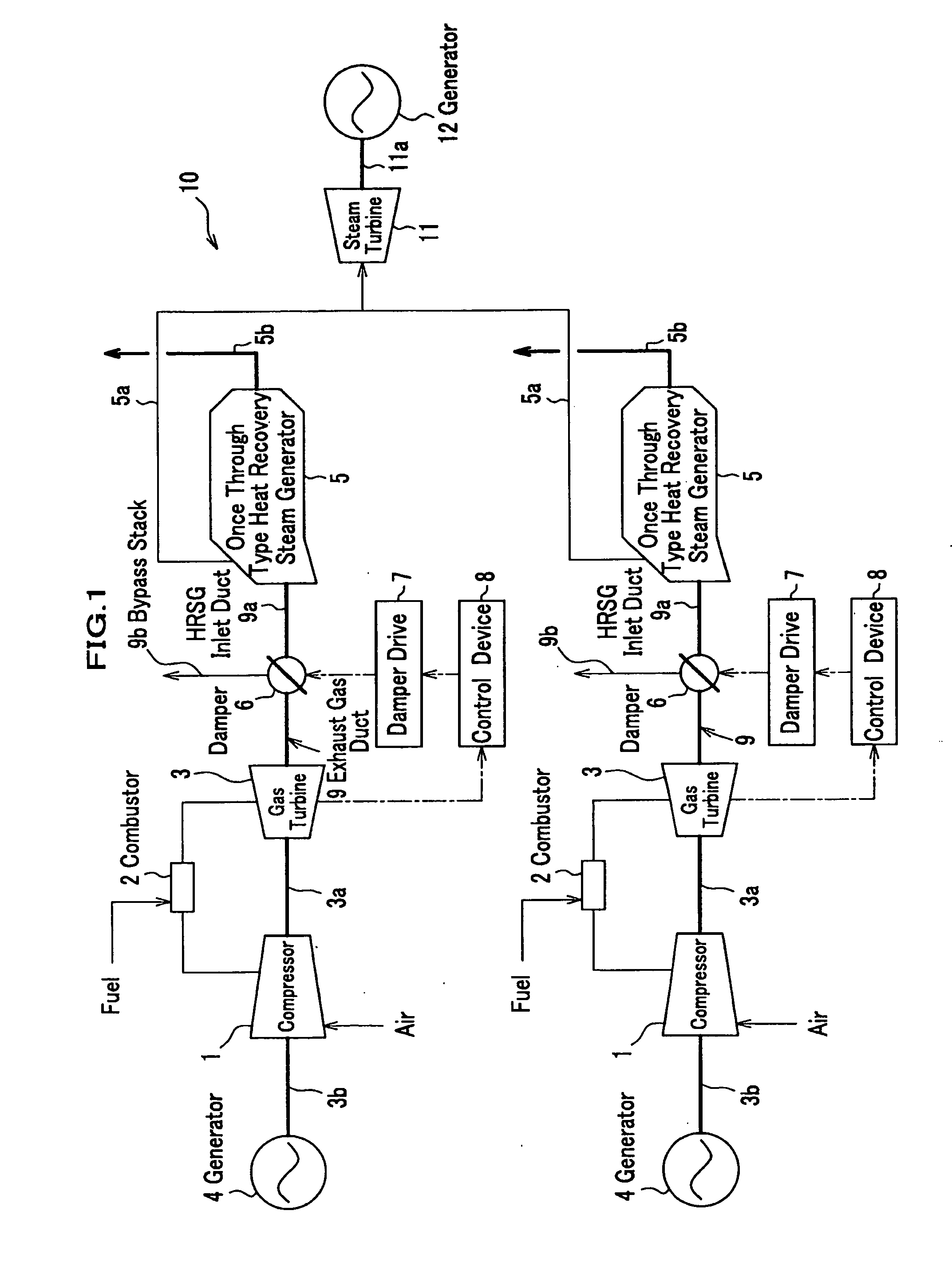
[0028] As shown in FIG. 1, a combined cycle power plant 10 comprises compressors 1, combustors 2, gas turbines 3, once through type heat recovery steam generators 5, and a steam turbine 11. Meanwhile, although the combined cycle power plant 10 shown in FIG. 1 is a configuration of two systems, it is not limited thereto; it may also be one system, and also not less than three systems.

[0029] Each of the gas turbine 3 is coupled to the compressor 1 through a rotor 3a; the compressor 1 is coupled to a generator 4 through a rotor coupling 3b. The compressor 1 compresses sucked air and sends it to the combustor 2. The combustor 2 mixes the compressed air and supplied fuel, combusts them, and produces a high temperature / high pressure combustion gas. At this time, the gas turbine 3 is rotationally driven by the combustion gas produced, the generator 4 is rotationally driven by a rotation torque of the gas turbine 3 through the rotor 3a and the rotor coupling 3b, and thus a power output is ...

second embodiment

[0060]FIG. 5 is a schematic perspective drawing showing part of a combined cycle power plant of a second embodiment of the present invention. Meanwhile, in the embodiment, because part excluding exhaust gas ducts 9A, 9B is same as in the first embodiment, same symbols are appended and descriptions thereof are omitted.

[0061] In the second embodiment the exhaust gas ducts 9A, 9B are provided between the gas turbine 3 and the once through type heat recovery steam generator 5. In one exhaust gas duct 9A are provided a HRSG inlet duct 9a1 and a bypass stack 9b1; in the other exhaust gas duct 9B are provided a HRSG inlet duct 9a2 and a bypass stack 9b2. Meanwhile, a form of the exhaust gas ducts 9A, 9B is not limited thereto, and for example, may be a fork-form where inlets of the exhaust gas ducts 9A, 9B are integrated.

[0062] In the exhaust gas ducts 9A, 9B are provided dampers 15a, 15b and guide lanes 16a, 16b functioning as a guide mechanism. The dampers 15a, 15b are provided at a po...


PUM


Abstract

A combined cycle power plant of the present invention is configured of a compressor; a combustor for combusting compressed air compressed by the compressor together with supplied fuel; a gas turbine driven by a combustion gas exhausted from the combustor; a heat recovery steam generator for recovering high temperature exhaust heat exhausted from the gas turbine; a steam turbine driven by steam obtained from the heat recovery steam generator; and an exhaust gas duct having an HRSG inlet duct that is provided between the gas turbine and the heat recovery steam generator and introduces an exhaust passage into the heat recovery steam generator, and a bypass stack that leads the exhaust gas outside, wherein the exhaust duct is configured of a damper, a damper drive for changing any of angle and opening of the damper, and a guide mechanism for preventing a vibration of the damper.

Description

BACKGROUND OF THE INVENTION [0001] 1. Field of the Invention [0002] The present invention relates to a combined cycle power plant that can generate power not only with driving a gas turbine but also with using heat of an exhaust gas from the gas turbine and driving a steam turbine. [0003] 2. Description of the Related Art [0004] These years, from a viewpoint of a resource saving and environment protection is adopted a combined cycle power generation that improves a power generation efficiency with combining a gas turbine and a steam turbine that uses exhaust heat thereof. A combined cycle power plant that uses the combined cycle power generation is configured by combining the gas turbine, the steam turbine, a heat recovery steam generator, and the like. If the gas turbine is driven, it is designed that an exhaust gas exhausted from the gas turbine is introduced into the heat recovery steam generator, and that the steam turbine is driven with steam produced by the heat recovery steam...

Claims


Application Information

Patent Timeline
Patent Type & Authority Applications(United States)
IPC IPC(8): F01D17/00F01D25/30F01K23/10F02C6/18F02C7/00F02C9/16F22B1/18
CPCF02C9/16F22B1/1815F05D2260/50F05D2260/85Y02E20/16
Inventor KURIHARA, TADASHISHIGENAKA, TOSHINORITAKENAGA, KAZUHIRONAGAI, SHOJITANIGUCHI, SHINICHI
Owner THE TOKYO ELECTRIC POWER CO INC
Why Eureka
Try Eureka