Method for welding a metal foil to a cylindrical metal pin

a metal foil and cylindrical technology, applied in the manufacture of electrode systems, electric discharge tubes/lamps, capacitors, etc., can solve the problem of replacing welding electrodes, and achieve the effect of simplifying the alignment of lasers and increasing bearing surface area

Inactive Publication Date: 2005-12-08
OSRAM GMBH
View PDF7 Cites 11 Cited by
  • Summary
  • Abstract
  • Description
  • Claims
  • Application Information

AI Technical Summary

Benefits of technology

[0003] The object of the invention is to provide an improved method for welding a metal foil to a cylindrical metal pin which avoids the abovementioned drawbacks.
[0007] To prevent the molten material from contracting and forming hump-like elevations on account of the surface tension, which would make it impossible to form an areal join to the metal pin, the laser is operated in pulsed mode, and the duration of the laser pulses is set to a value of less than or equal to 1.0 millisecond. The diameter of the laser beam is advantageously matched to the width or transverse dimension of the contact region of metal foil and metal pin, in order to ensure that the heat which is generated by the laser is transmitted to the material of the metal pin, so that it is impossible for any holes to form in the metal foil as a result of overheating. Therefore, a laser with a beam diameter of less than or equal to 0.5 millimeter is advantageously used to weld the metal pins which are customarily used in lamp engineering. Furthermore, it has proven advantageous for the metal pin to be flattened prior to the welding process and for the surface of the metal pin which has been formed by this flattening operation to be brought into contact with the metal foil. Flattening the metal pin increases the bearing surface area between the metal foil and the metal pin. Accordingly, the two metal parts can be joined to one another by a greater number of weld spots, and alignment of the laser is simplified. To ensure a sufficient contact pressure over the entire contact surface between metal foil and metal pin, avoiding any spaces between them, and also to make the entire contact surface accessible to the welding process, the contact pressure is advantageously generated by means of a continuous gas stream, which is directed onto the metal foil during the welding process, or by a suitable mechanical pressure-exerting device.

Problems solved by technology

This method has the drawback that the welding electrodes have to be replaced at regular intervals, on account of becoming worn, which interrupts the production process.

Method used


Image

  • Method for welding a metal foil to a cylindrical metal pin
  • Method for welding a metal foil to a cylindrical metal pin
  • Method for welding a metal foil to a cylindrical metal pin

Examples


Embodiment Construction

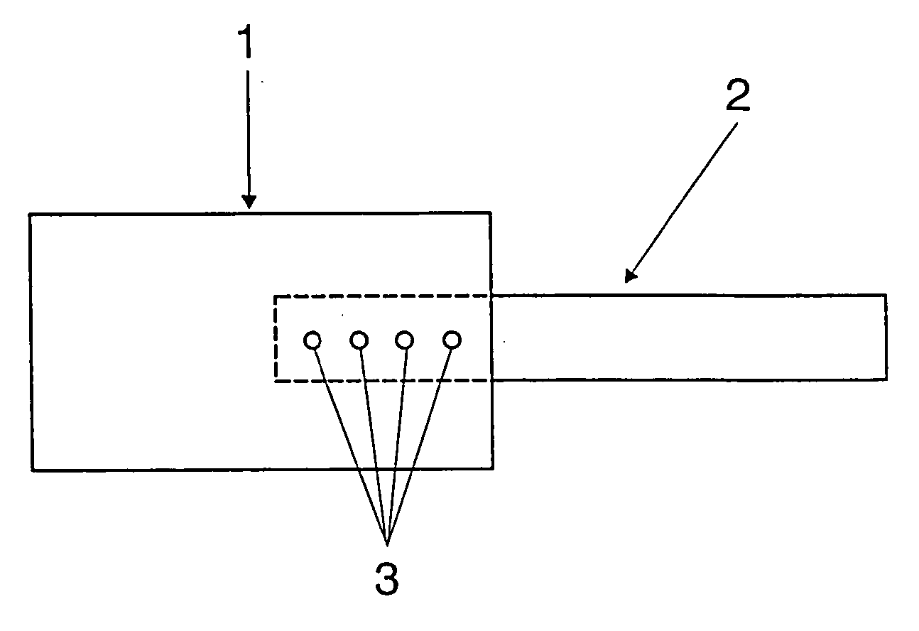
[0011] The molybdenum foil 1 illustrated in FIG. 1 is 27 μm thick. The molybdenum pin 2 is cylindrical in form and has a diameter of 0.78 mm. To be welded together, the molybdenum foil 1 and the molybdenum pin 2 are clamped in a holder, arranged such that they overlap and are in contact with one another. The four weld spots 3 are produced with the aid of a neodymium:yttrium aluminum garnet laser, which generates infrared radiation with a wavelength of 1064 nm. The laser is operated in pulsed mode with a mean power of 100 Watts and a peak pulse power of 8 kilowatts. The duration of the pulses is preferably 0.5 ms. The diameter of the laser beam is 0.1 mm. The four weld spots are arranged in a row, at intervals of 0.5 mm. To produce the four weld spots 3, the laser is directed onto the surface of the molybdenum foil 1 remote from the molybdenum pin 2, in each case onto a spot of the contact surface between molybdenum foil 1 and molybdenum pin 2, and at this spot the material of the mo...


PUM

PropertyMeasurementUnit
diameteraaaaaaaaaa
thicknessaaaaaaaaaa
diameteraaaaaaaaaa

Abstract

The invention relates to a method for welding a metal foil to a metal pin, these components being intended for use as supply conductors in lamps, the metal foil being pressed onto the metal pin in order for the welding process to be carried out, and the region of the metal foil which adjoins the metal pin is heated and melted in punctiform fashion at a plurality of locations via a laser, so that after the molten material has cooled, the metal foil and the metal pin are joined to one another in the vicinity of these locations.

Description

I. TECHNICAL FIELD [0001] The invention relates to a method for welding a metal foil to a cylindrical metal pin, which components are intended for use as supply conductors in lamps. II. BACKGROUND ART [0002] Laid-Open specification EP 1 066 912 A1 describes the welding of a molybdenum foil to a cylindrical tungsten pin by means of a resistance weld. This method has the drawback that the welding electrodes have to be replaced at regular intervals, on account of becoming worn, which interrupts the production process. III. DISCLOSURE OF THE INVENTION [0003] The object of the invention is to provide an improved method for welding a metal foil to a cylindrical metal pin which avoids the abovementioned drawbacks. [0004] This object is achieved by a method for welding a metal foil to a metal pin, these components being intended for use as supply conductors in lamps, the metal foil being pressed onto the metal pin in order for the welding process to be carried out, wherein the region of the...

Claims


Application Information

Patent Timeline
Patent Type & Authority Applications(United States)
IPC IPC(8): B23K26/20B23K26/06B23K26/22B23K101/38B23K103/08H01J9/28H01J61/36H01K1/20H01K1/40H01K3/00H01K3/06
CPCH01K3/00B23K26/063B23K26/22B23K2201/32H01K1/40B23K2203/08H01J9/28H01J61/36B23K2201/36B23K26/0622B23K2101/32B23K2101/36B23K2103/08
Inventor RITTNER, ROLAND
Owner OSRAM GMBH
Why Eureka
Try Eureka