Switch

a switch and switch technology, applied in the field of switches, can solve the problems of inability to achieve the desired value of the response time, the inability to guarantee the stability of the switch operation characteristic, and the increase of the application voltage, so as to achieve the effect of reducing the characteristic change and speed

Inactive Publication Date: 2005-12-08
PANASONIC CORP
View PDF10 Cites 16 Cited by
  • Summary
  • Abstract
  • Description
  • Claims
  • Application Information

AI Technical Summary

Benefits of technology

[0012] According to this structure, an electrostatic force is caused between the first and second beams to thereby move both of the first and second beams so that the beams can be coupled together at high speed and put off at high speed. By causing an electrostatic force on the third beam arranged facing to the second beam and previously placing it close to the first and second beams, a strong electrostatic force can be applied between the second and third beams, enabling to make a response at higher spee

Problems solved by technology

However, because electrostatic force is proportional to a negative square of distance, electrostatic force decreases and makes it impossible for response time to attain a desired value.
However, application voltage increase is not preferred for the radio communication device requiring low power consumption and low drive voltage.
Furthermore, at an elevated temperature, beam internal stress turns into compression, possibly causing buckling.
Namely, unless the residual stress resulting from a manufacture process or environmental temperature upon switch op

Method used


Image

  • Switch
  • Switch
  • Switch

Examples


first exemplary embodiment

1. First Exemplary Embodiment

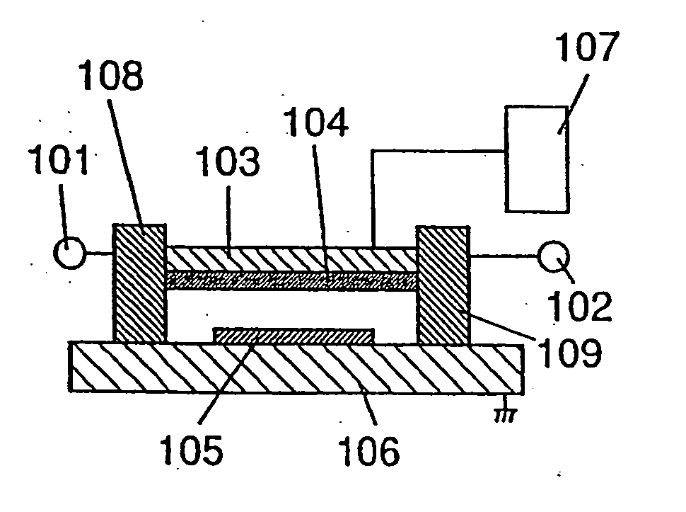
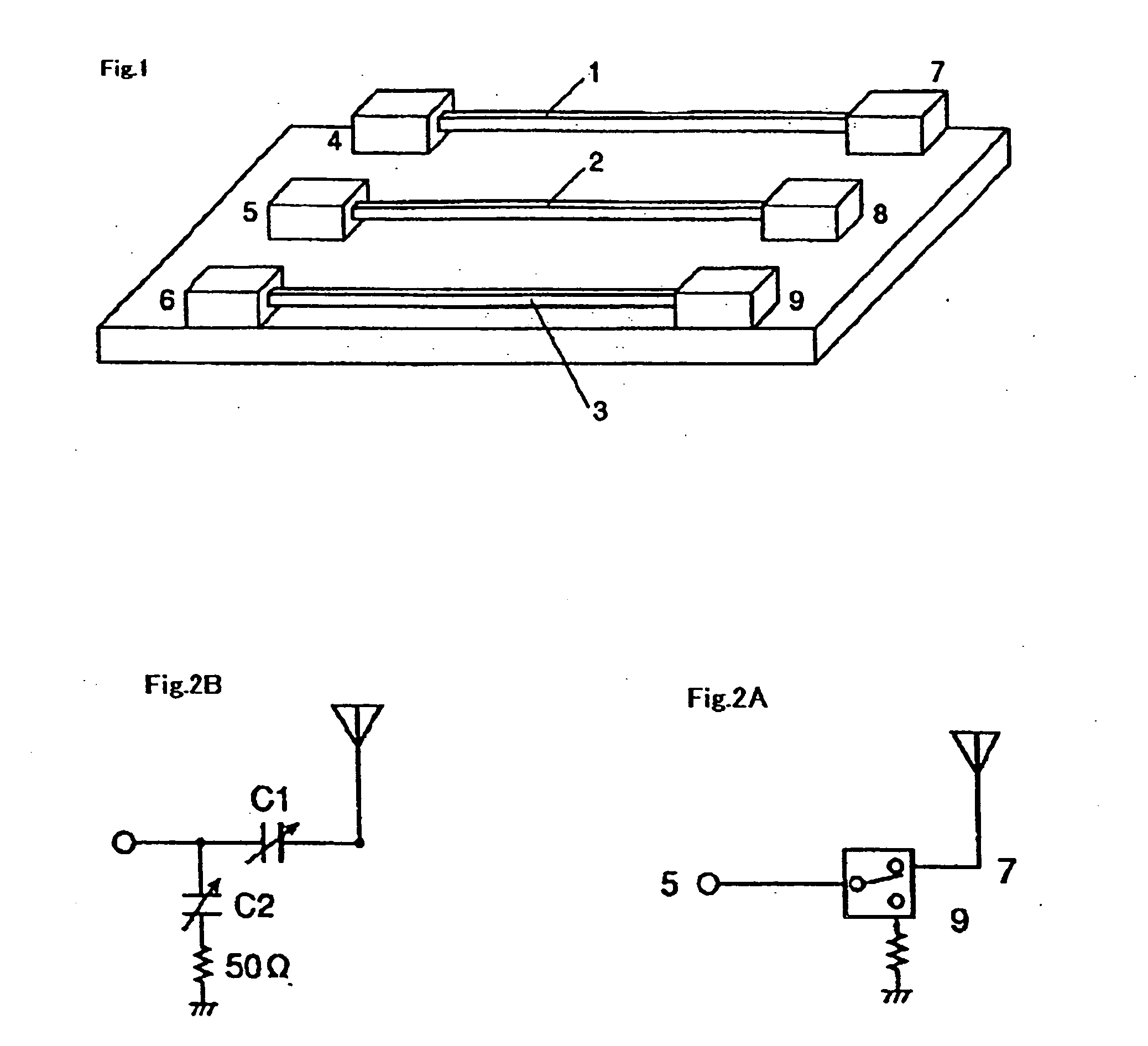
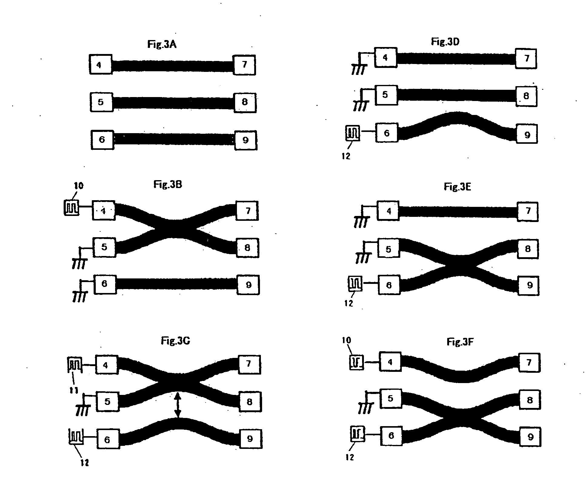
[0033] With reference to FIGS. 1 to 3, explained is embodiment 1 of the invention. FIG. 1 depicts a schematic structural view of a switch according to embodiment 1. A first beam 1, second beam 2, third beam 3 is formed of such a shape and material as transferring an electric signal with no loss, having an insulation film with approximately 10 nm on a surface thereof. The beam 1, 2, 3 is formed, for example, of a metal, such as Al, Au, Cu or an alloy, having a shape in a both-ends-supported beam structure having a thickness 2 μm, a width 2 μm and a length 200 μm and supported at both ends. These are arranged parallel at such a spacing, e.g. of 0.6 μm, to satisfy a given isolation. The beam 1, 2, 3 is not necessarily a both-ends-supported beam structure but may be a cantilever form. Meanwhile, the beam 1, 2, 3 has a beam spring constant to be varied by changing the shape. Incidentally, the beam 1, 2, 3 is based on a structure and process to reduce its inte...

second exemplary embodiment

2. Second Exemplary Embodiment

[0060] Now a second embodiment is explained while referring to FIG. 5. This embodiment is basically the same in structure as the first embodiment. However, a second beam 32 is formed smaller in thickness as compared to the first beam 31 and third beam 33, e.g. the first and third beams are formed 1.5 times greater in thickness than the second beam. In this embodiment, when the first beam 31 and the second beam 32 come into contact, an electrostatic force 35 acts between the first beam 31 and the third beam 33 in addition to an electrostatic force 34 acting between the first beam 31 and the second beam 32. With this structure, even unless a direct current potential is newly applied to the electrode 6 after a contact between the first beam 31 and the second beam 32 as was in the first embodiment, the third beam 33 is to move toward the second beam 32.

[0061] In such a case, in order for the first beam 31 to near toward the third beam 33 to a possible clos...

third exemplary embodiment

3. Third Exemplary Embodiment

[0062] Now a third embodiment is explained while referring to FIGS. 6 and 7. This embodiment has a plurality (four in FIG. 6) of FIG. 2A switch circuits symmetrically about an antenna end 65, as shown in FIG. 6. This can realize a one-input multi-output switch that can distribute an input to one antenna into a plurality of outputs and multi-output them. The switch thus structured can be configured by arraying the switches used in embodiment 1 and capacitively coupling those as shown in FIG. 7. Incidentally, FIG. 7 shows a case having two switch circuits. In FIG. 7, an electrode 71 is formed with a plurality of beams 74 in a comb form, having beams 75 between the beams 74. The beams 75 are respectively coupled with electrodes 72. An electrode 73 is provided oppositely to the electrodes 72. The electrode 71 is connected with a control voltage source 76, the electrode 72 with a control voltage source 77 and the electrode 73 is with control voltage source 78...


PUM


Abstract

A switch comprises voltage applying means for providing direct current potentials to first to third beams arranged with a spacing slightly distant one from another, and electrodes for inputting/outputting signals to/from the beams. By controlling the direct current potential provided to the beam, an electrostatic force is caused to thereby change the beam positions and change a capacitance between the beams. By causing an electrostatic force between the first and second beams and moving the both beams, the first and second beams can be electrically coupled together at high speed. Also, an electrostatic force is caused on the third beam arranged facing to the first and second beams, to previously place it close to the first and second beams. When the electrostatic force is released from between the first and second beams, the second beam moves toward the third beam thereby releasing the first and second beams of an electric coupling.

Description

FIELD OF THE INVENTION [0001] This invention relates to a switch, for use on an electric circuit, having an electrode to be mechanically moved by an externally applied force, to thereby pass or cut off the signal. BACKGROUND OF THE INVENTION [0002] Conventionally there is known, as a switch for use on an electric circuit, a switch using an air bridge described in USP6218911. In this structure, a movable air bridge is arranged between a pair of electrodes formed on a substrate. In case an electrostatic force is given between the electrode and the movable air bridge, the air bridge horizontally moves toward the electrode into a contact with one electrode but isolated from the other electrode. Accordingly, in case a signal is inputted to the air bridge, the air bridge is electrically connected with the one electrode, allowing a signal to pass. However, the signal is cut off at the other electrode, thus enabling switch operation. [0003] Meanwhile, a micro-electromechanical RF switch is ...

Claims


Application Information

Patent Timeline
IPC IPC(8): B81B3/00H01H49/00H01H59/00
CPCH01H59/0009H01G5/40H01H2059/0027H01H2001/0078
Inventor NAKANISHI, YOSHITOSHIMIZU, NORISATONAKAMURA, KUNIHIKONAITO, YASUYUKI
Owner PANASONIC CORP
Why Eureka
Try Eureka