
Heart wall ablation/mapping catheter and method

a catheter and catheter technology, applied in the field of catheters, can solve the problems of ignoring symptoms, unable to cure the underlying, and requiring implantable electrical stimulators,

Inactive Publication Date: 2005-12-08
MEDTRONIC INC
View PDF99 Cites 63 Cited by
  • Summary
  • Abstract
  • Description
  • Claims
  • Application Information

AI Technical Summary

Benefits of technology

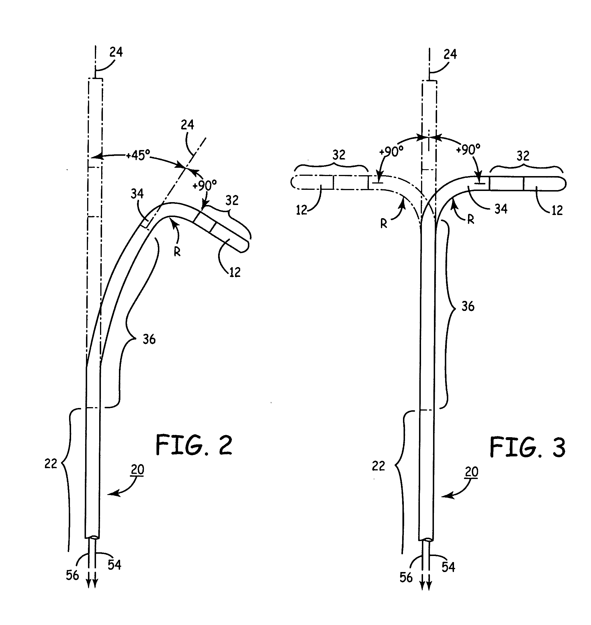
[0011] The present invention is directed to a steerable catheter for mapping and / or ablation that comprises a catheter body having a proximal section and a distal section, a handle coupled to he proximal end of the catheter body, and manipulators that enable the deflection of a distal segment of the distal tip section with respect to a proximal segment of the distal tip section or the proximal section. The manipulators enable independently imparting a curvature of the proximal segment and a bending or knuckle motion of an intermediate segment between the proximal and distal segments. A wide angular range of deflection within a very small knuckle curve or bend radius in the intermediate segment is obtained. At least one distal tip electrode is preferably confined to the distal segment which can have a straight distal segment axis or can have a pre-formed curvature of the distal segment axis extending distally from the intermediate segment.

Problems solved by technology

While drugs may be the treatment of choice for many patients, drugs typically only mask the symptoms and do not cure the underlying cause.
Implantable electrical stimulators, e.g., pacemakers, afferant nerve stimulators and cardioverter / defibrillators, usually can only correct an arrhythmia after it occurs and is successfully detected.
Ablation of VT's can be difficult due to the thickness of the ventricular chamber walls.
Typical RF delivery through standard electrodes is not capable of creating deep transmural lesions in the ventricles.
When RF power is raised to high levels, tissue charring and subsurface steam explosions can occur.
Coagulum buildup on the electrode surfaces leads to high impedance problems and more importantly, thrombi may be released that could cause stroke.
These factors present major problems that limit the safe depth to which lesions can be created.
With irrigated RF ablation, there remains the problem of creating excessive subsurface temperatures that can lead to steam explosions and cratering of the endocardium.
While EP mapping and RF ablation catheters having the aforementioned deflectability and steerability have had promising results, such catheters suffer from certain disadvantages.
The degree of deflection of the distal segment with respect to the proximal segment is limited, and the curves that can be obtained in the distal segment are limited.
Moreover, the limited curvature or angular displacement of the distal segment with respect to the proximal segment and the proximal section of the catheter body does not make it possible to optimally apply the distal tip electrode(s) against other target points or sites of the heart wall or endocardium.

Method used


Image

  • Heart wall ablation/mapping catheter and method
  • Heart wall ablation/mapping catheter and method
  • Heart wall ablation/mapping catheter and method

Examples


Embodiment Construction

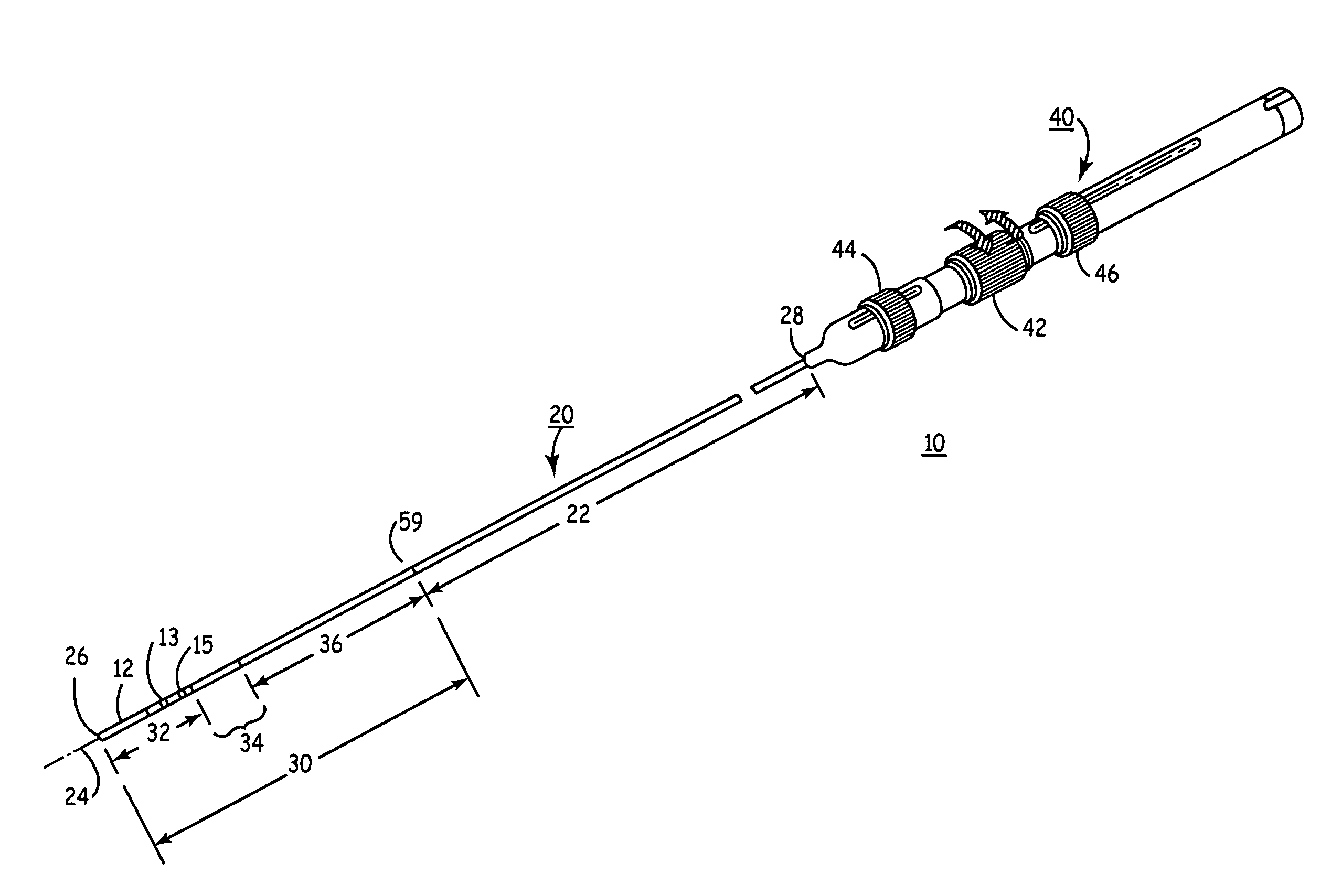
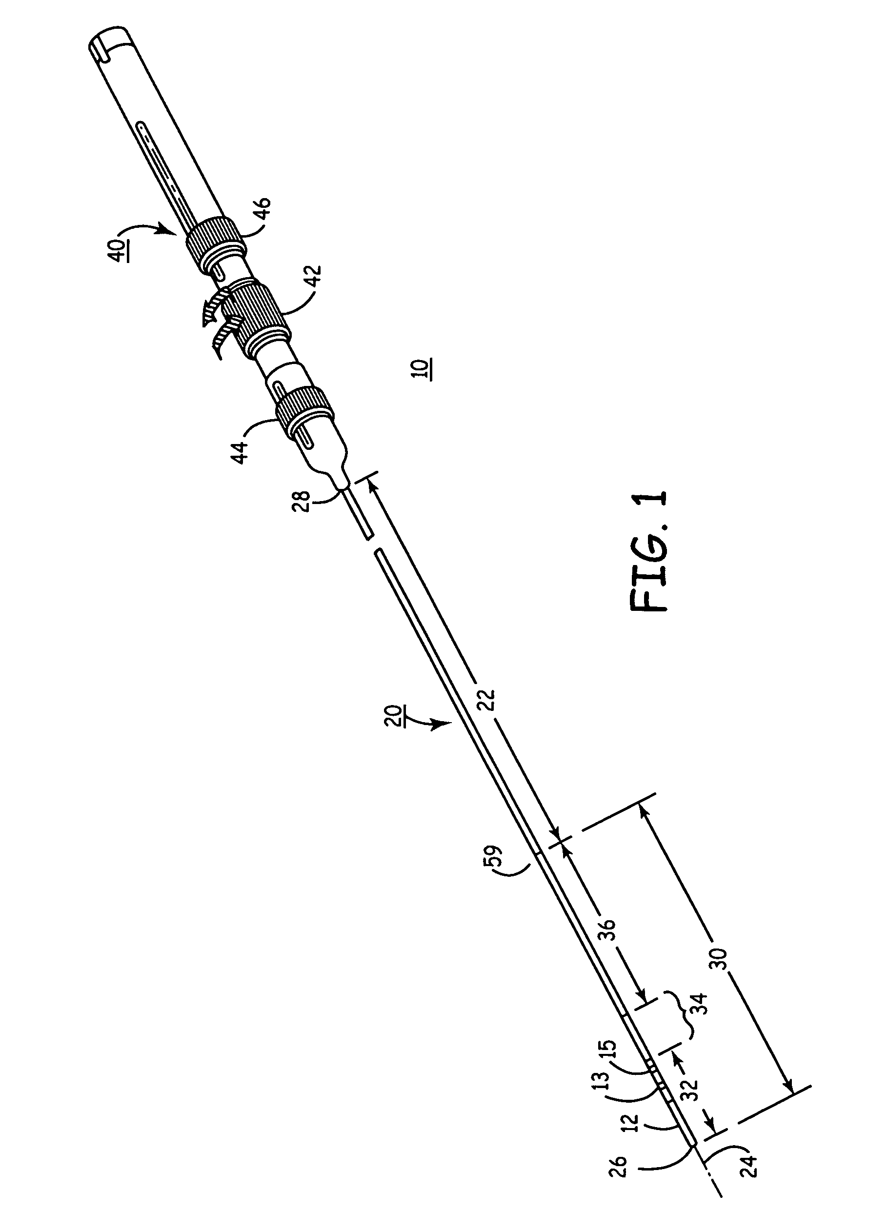
[0037]FIG. 1 schematically illustrates an anatomically-conforming, multi-curve catheter 10 incorporating various features of the present invention for orienting a distal tip electrode 12 (or electrodes) with respect to the heart wall for RF ablation and / or EP mapping. The multi-curve catheter 10 can incorporate a porous tip and catheter lumen for emitting irrigating fluid around the distal tip electrode 12, but those features are not illustrated in FIG. 1 to simplify illustration. Moreover, the distal segment 32 is simplified in FIG. 1 to show an elongated tubular shaped ablation electrode 12 and a pair of mapping electrodes 13 and 15 in the illustration of FIG. 1, but the distal segment 32 may comprise a plurality of ring-shaped electrodes, one or more coil electrode or the like having other shapes that are presently used or may come into use and including several variations described below in reference to other figures. It will be understood that the catheter 10 also represents an...


PUM


Abstract

Steerable electrophysiology catheters for use in mapping and / or ablation of accessory pathways in myocardial tissue of the heart wall and methods of use thereof are disclosed. The catheter comprises a catheter body and handle, the catheter body having a proximal section and a distal section and manipulators that enable the deflection of a distal segment of the distal tip section with respect to the independently formed curvature of a proximal segment of the distal tip section through a bending or knuckle motion of an intermediate segment between the proximal and distal segments. A wide angular range of deflection within a very small curve or bend radius in the intermediate segment is obtained. At least one distal tip electrode is preferably confined to the distal segment which can have a straight axis extending distally from the intermediate segment. The curvature of the proximal segment and the bending angle of the intermediate segment are independently selectable. The axial alignment of the distal segment with respect to the nominal axis of the proximal shaft section of the catheter body can be varied between substantially axially aligned (0° curvature) in an abrupt knuckle bend through a range of about −90° to about +180° within a bending radius of between about 2.0 mm and 7.0 mm and preferably less than 5.0 mm. The proximal segment curve can be independently formed in a range of about −180° through about +270° with respect to the axis of the proximal shaft section to provide an optimum angular orientation of the distal electrode(s). The distal segment can comprise a highly flexible elongated distal segment body and electrode(s) that conform with the shape and curvature of the heart wall.

Description

FIELD OF THE INVENTION [0001] The present invention relates generally to steerable catheters, and more specifically to steerable electrophysiology catheters for use in mapping and / or ablation of accessory pathways in myocardial tissue of the heart wall. BACKGROUND OF THE INVENTION [0002] The heart includes a number of pathways through which electrical signals necessary for normal, electrical and mechanical synchronous function or the upper and lower heart chambers propagate. Tachycardia, that is abnormally rapid rhythms of the heart, are caused by the presence of an arrhythmogenic site or accessory pathway which bypasses or short circuits the nodal pathways in the heart. Tachycardias may be categorized as ventricular tachycardias (VTs) or supraventricular tachycardias (SVTs). The most common SVT's include atrioventricular nodal reentrant tachycardia (AVNRT), Atrioventricular reentrant tachycardia (AVRT), atrial fibrillation (AF), and atrial flutter (AFI). Reentrant tachycardias orig...

Claims


Application Information

Patent Timeline
Patent Type & Authority Applications(United States)
IPC IPC(8): A61B17/00A61B18/14A61M25/01
CPCA61B18/1492A61B2017/00243A61B2018/00916A61M25/0147A61M25/0152A61M2025/015A61M2025/0161
Inventor STEWART, MARK T.GOODE, JOHNSON E.SPECKIEN, JAMES M.TAUBE, MARK A.WARMAN, EDUARDO N.
Owner MEDTRONIC INC
Learn More