Organic electroluminescence display apparatus

Inactive Publication Date: 2005-12-15
PANASONIC LIQUID CRYSTAL DISPLAY CO LTD +1
View PDF6 Cites 58 Cited by
  • Summary
  • Abstract
  • Description
  • Claims
  • Application Information

AI Technical Summary

Benefits of technology

[0064] It is known that the emission life of an organic EL display apparatus degrades due to moisture. However, a moisture adsorbing function allows for a desiccant, whic

Problems solved by technology

Applying the technology disclosed in JP-A-2003-257622 to an active-matrix organic EL display apparatus having a top emission structure in particular, suffers from the following problem.
For example, since for a blue filter only blue light is transmitted from among the white light, at least ⅔ of the incident light is unavoidably lost (same for the green or red filters), giving rise to the problem that the transmitted light attenuates to ⅓, whereby performance in terms of display brightness is dependent on the emission brightness of the white color EL material.
Applying the technology disclose

Method used


Image

  • Organic electroluminescence display apparatus
  • Organic electroluminescence display apparatus
  • Organic electroluminescence display apparatus

Examples


example 1

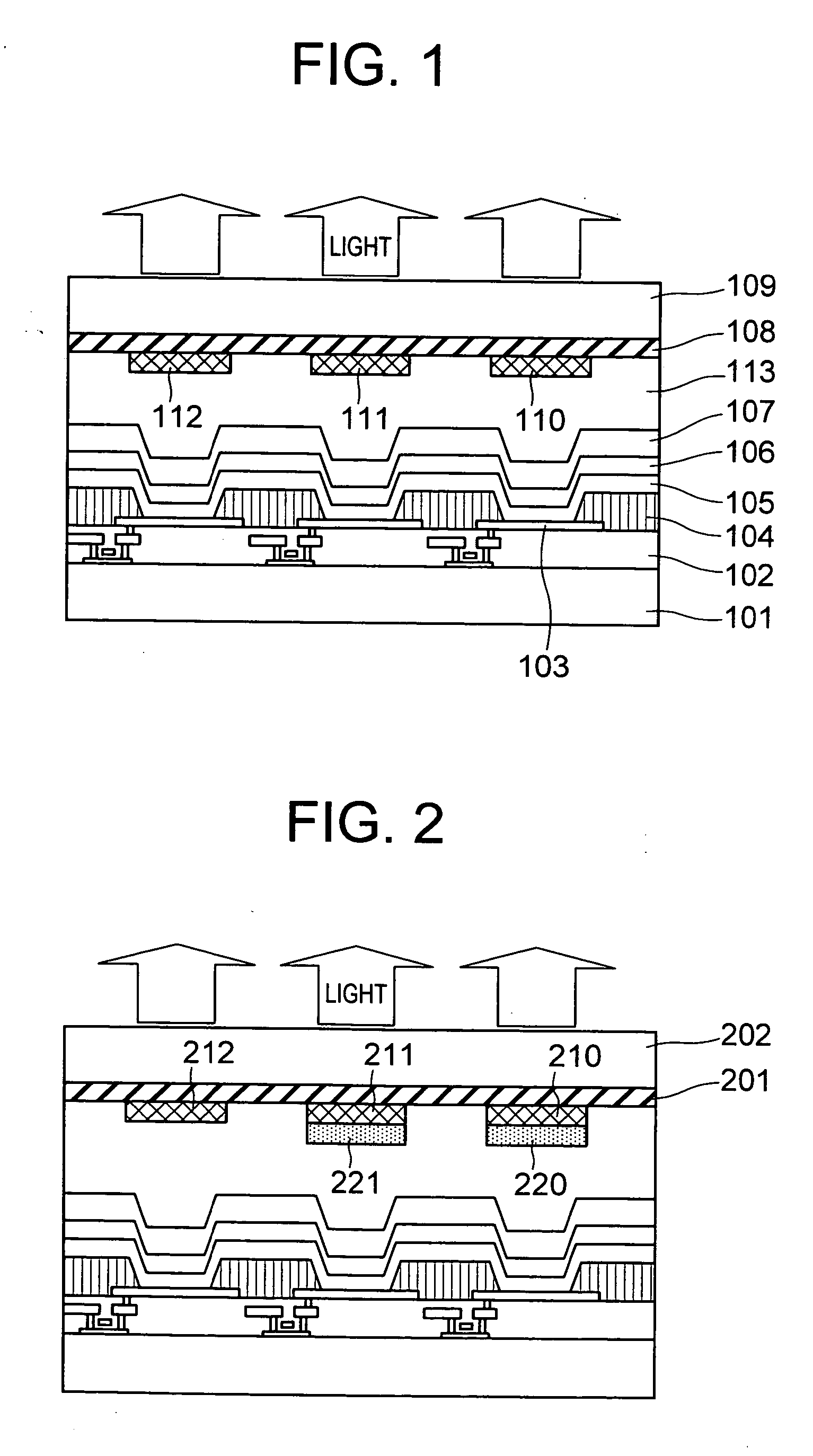
[0080] As one example of the organic EL display apparatus according to the present invention, an active-matrix organic EL display apparatus will be explained using the cross-sectional view illustrated in FIG. 1.

[0081] A thin-film transistor (TFT) element circuit layer 102 formed with a thin-film transistor and electrode wiring was formed on a non-alkali glass substrate 101. Electrodes 103 sandwiching an organic EL layer 105 were separated by pixel units of an active-matrix organic EL display apparatus by a separating insulation film 104. The white color organic EL layer 105 was formed over the entire surface of the electrodes 103 and the separating insulation film 104, and a transparent electrode 106 was formed over that entire surface. Above this, an inorganic insulation film 107 was coated having gas barrier properties so that moisture or oxygen was not transmitted therethrough.

[0082] The TFT element circuit layer 102 was formed from a TFT employing amorphous silicon or low-temp...

example 2

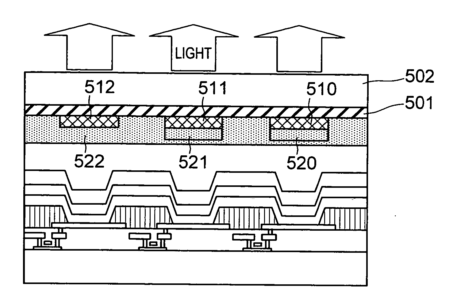
[0114] Next, as one example of the organic EL display apparatus according to the present invention, an organic EL display apparatus provided with a color conversion filter will be explained using the substrate cross-sectional view illustrated in FIG. 2.

[0115] Since the difference between FIG. 2 and Example 1 as illustrated in FIG. 1 lies in the structure of the opposing transparent substrate 202, this point will now be explained.

[0116] To achieve full color display by splitting the emissions from the white color organic EL layer, an opposing transparent substrate 202 was formed with red, green and blue filter patterns (210, 211, 212), and red and green conversion filter patterns (220, 221). Between these filter patterns and the opposing transparent substrate 202 was formed a porous insulation film 201.

[0117] In this case the porous insulation film 201 was an insulation film which contained SiO and possessed the above-described characteristics (1) through (6). An insulation film w...

example 3

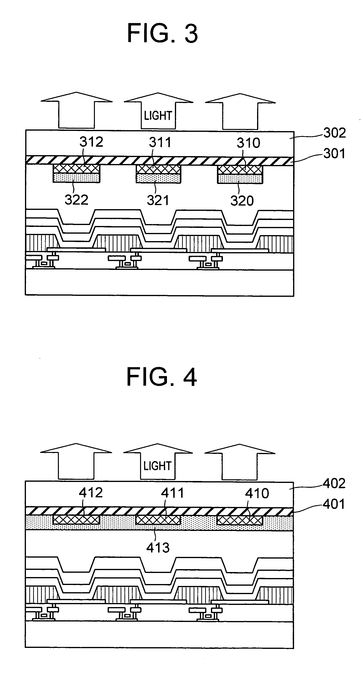
[0126] Next, as one example of the organic EL display apparatus according to the present invention, an organic EL display apparatus provided with a color conversion filter will be explained using the substrate cross-sectional view illustrated in FIG. 3.

[0127] Since the difference between FIG. 3 and Example 1 as illustrated in FIG. 1 lies in the structure of the opposing transparent substrate 302, this point will now be explained.

[0128] To achieve full color display by splitting the emissions from a white color organic EL layer, an opposing transparent substrate 302 was formed with red, green and blue pigment dispersion color filter patterns (310, 311, 312), and red, green and blue conversion filter patterns (320, 321, 322). Between these filter patterns and the opposing transparent substrate 302 was formed a porous insulation film 301.

[0129] In this case, the porous insulation film 301 was an insulation film which contained SiO and possessed the above-described characteristics (1...


PUM


Abstract

The color filter is a color conversion filter having a color conversion function, wherein white light is emitted from an organic EL to the color filter, transmitted through the color filter, and thereby split into three colors of blue, green and red. At such time, through the absorption of shorter wavelength light that is not usually transmitted through the color filter and through the emission of light having a longer wavelength than that of the absorption region, the transmitted light of the color filter is added to the emitted light to increase brightness. In addition, between the color filter and the transparent substrate, a porous insulation film is formed, wherein the film has a refractive index smaller than that of the transparent substrate, and has that nanopores, so that light-scattering effects can be achieved, and the transmitted light of the color filter is coupled out efficiently to the outside. Use of such a configuration realizes a top-emission structure organic EL display apparatus in which a white color emission organic EL is combined with color filter to achieve full color display, wherein white light emitted from the organic EL is converted and split by the color filter and thereby coupled out efficiently to the outside.

Description

INCORPORATION BY REFERENCE [0001] The present application claims priority from Japanese application JP 2004-147167 filed on May 18, 2004, the content of which is hereby incorporated by reference into this application. BACKGROUND OF THE INVENTION [0002] The present invention relates to an organic electroluminescence display apparatus, and in particular, to a display apparatus which achieves color display by splitting into three primary colors light which have been emitted from an organic electroluminescence layer and transmitted through a color conversion filter formed on an opposing transparent substrate, the high performance organic electroluminescence display apparatus having improved coupling-out efficiency of emission from the transparent substrate. [0003] Unlike liquid-crystal display apparatuses which require a backlight, organic electroluminescence (hereinafter referred to as “organic EL”) display apparatuses, are self-luminescent. Since organic ELs are thinner than liquid cr...

Claims


Application Information

Patent Timeline
IPC IPC(8): H01L27/32H01L51/50H05B33/04H01L51/52H05B33/12H05B33/14H05B33/22
CPCH01L27/322H01L51/5268H10K59/38H10K50/854
Inventor TANAKA, JUNSEKIGUCHI, SHINJIOOTANI, MIHARUOGATA, KIYOSHI
Owner PANASONIC LIQUID CRYSTAL DISPLAY CO LTD
Why Eureka
Try Eureka