
Solid state turbine engine ignition exciter having elevated temperature operational capabiltiy

a technology of solid-state turbine engines and operational capabilities, which is applied in the direction of machines/engines, lighting and heating apparatus, instruments, etc., can solve the problems of increased power dissipation, limited thermal performance of current-art solid-state ignition exciters, and limited leakage current related limitations of switching devices, so as to achieve high reliability operation

Active Publication Date: 2005-12-15
WOODWARD GOVERNOR CO
View PDF59 Cites 12 Cited by
  • Summary
  • Abstract
  • Description
  • Claims
  • Application Information

AI Technical Summary

Benefits of technology

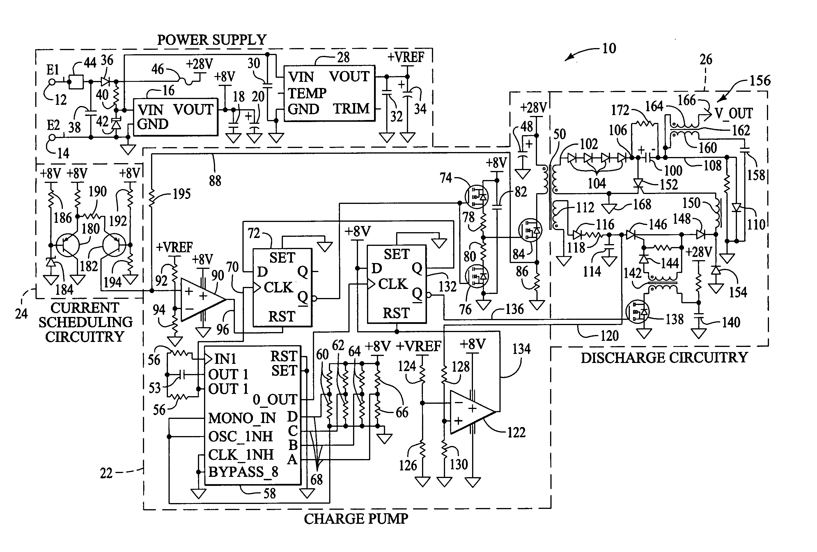
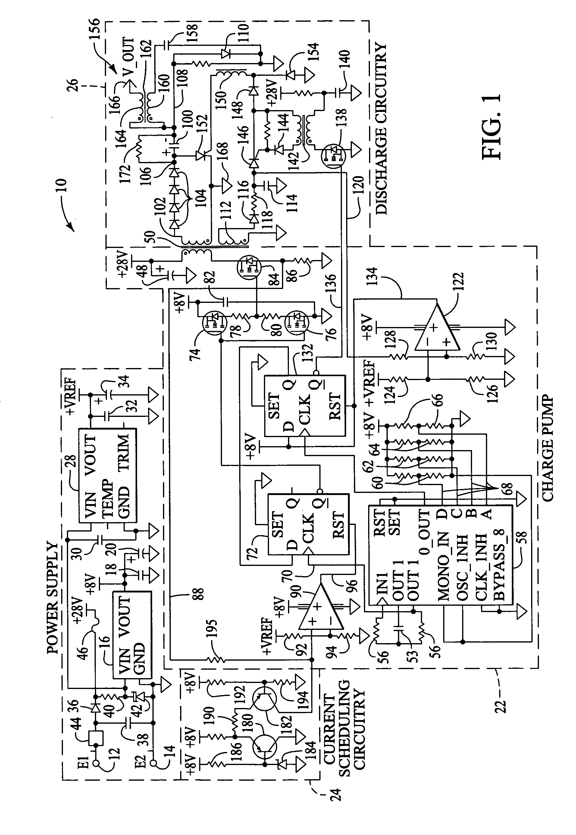
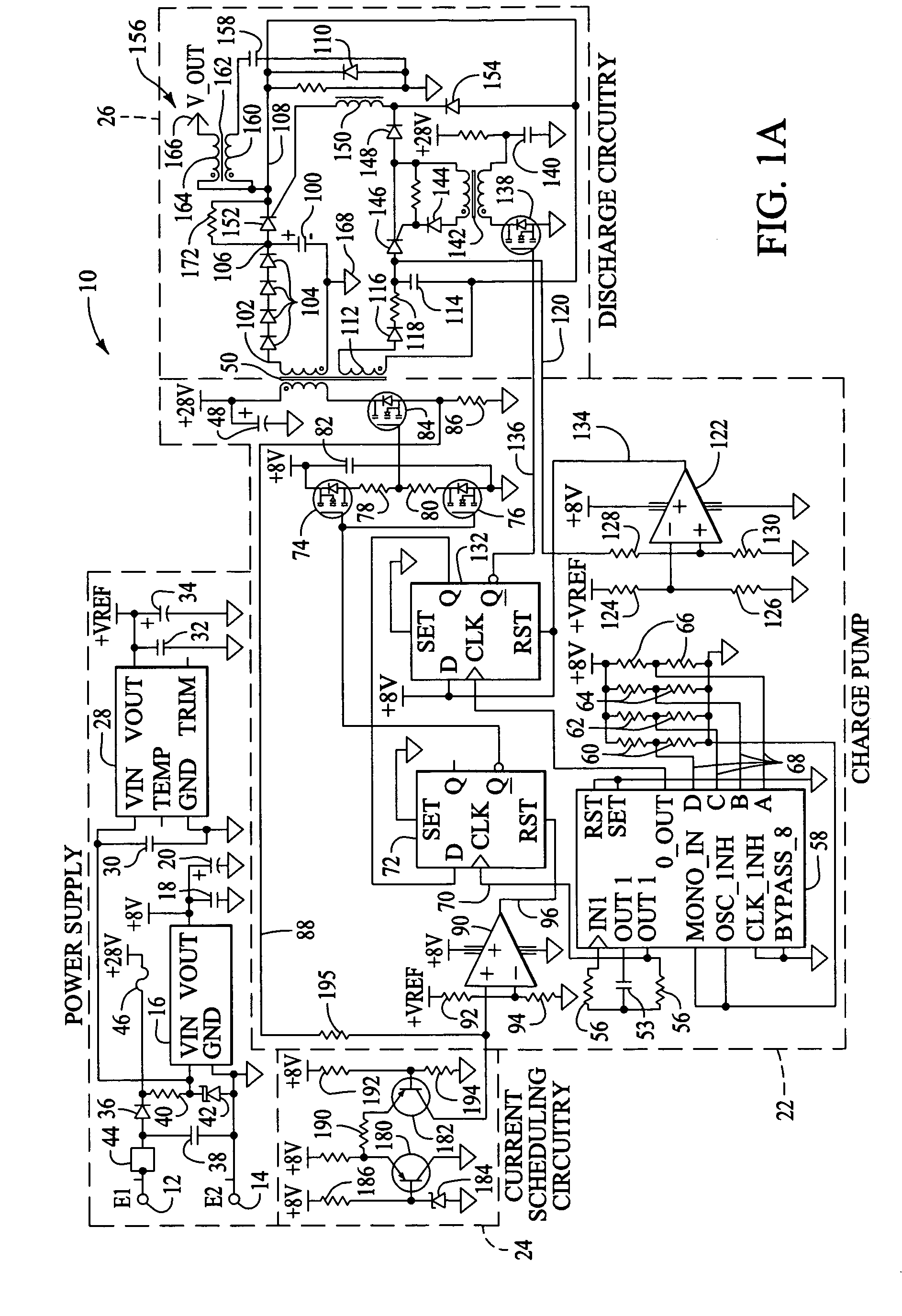
[0006] The first preferred embodiment of the present invention provides improved turbine engine ignition exciter technology that enables volumetrically efficient, lightweight, and high reliability operation at elevated ambient temperatures. The first preferred embodiment uses a semiconductor pulse switching device that is designed to exhibit low leakage current at elevated ambient temperatures and a low side switching topology that includes a discharge circuit for releasing energy from an energy store to ground whereby negative polarity energy is applied to the igniter. This embodiment uses a gate drive circuit that is specifically tuned for the particular exciter to insure a positive gate drive current in the switching device throughout the stressful modulation period.
[0007] The first preferred embodiment also includes circuitry for compensating for low input voltages applied to the exciter, which enables the exciter to reliably operate when low input voltages are experienced.

Problems solved by technology

Thermal performance of current art solid state ignition exciters has been limited due to available thyristor switching technology.
However, performance of both suffer from leakage current related limitations of the switching devices.
At elevated temperatures, leakage current within the switching device results in increased power dissipation.
This condition precipitates additional leakage current, resulting in a thermal runaway condition and device failure.
While a considerable improvement over phase control based designs, thermal performance of current art pulse thyristor based ignition exciters is still limited by switching device leakage current.
Moreover, current art technology incorporates costly semiconductor die manufacturing and device packaging techniques limiting commercial viability of the ignition exciters.

Method used


Image

  • Solid state turbine engine ignition exciter having elevated temperature operational capabiltiy
  • Solid state turbine engine ignition exciter having elevated temperature operational capabiltiy
  • Solid state turbine engine ignition exciter having elevated temperature operational capabiltiy

Examples


Embodiment Construction

[0023] Operation of current prior art turbine engine ignition exciters at elevated ambient temperatures is limited by semiconductor leakage current. At elevated ambient temperatures, semiconductor leakage current increases exponentially with temperature which results in increased switching device power dissipation. This reduces product reliability, and if not carefully accounted for in the design process, can result in system failure due to thermal runaway effects. That is, at extreme temperatures device dissipation causes further device heating, which in turn causes further dissipation which progresses exponentially until the device is destroyed. This condition is exacerbated by the relatively high (approximately 3 kV) exciter tank circuit voltages commonly used in turbine engine ignition systems. The first preferred embodiment of the present invention employs a relatively low (i.e., approximately 1.5 kV to approximately 1.95 kV) tank voltage to further reduce dielectric and leakag...


PUM


Abstract

A turbine engine ignition exciter circuit applies energy stored in the exciter tank capacitor to the load (igniter plug) through a thyristor type semiconductor switching device that minimizes leakage current at elevated operating temperatures. The semiconductor switching device is periodically activated by a trigger circuit to initiate discharge of energy stored in exciter tank capacitor to mating ignition lead and igniter plug. The circuit operates at a modest, for example, approximately 1.8 kV, tank circuit voltage to further reduce switching device leakage current related stresses at elevated temperatures allowing relatively long capacitor charge cycles, increased upper operating temperature capability and improved reliability. The circuit uses a low side switch circuit topology for releasing energy from said capacitor to ground whereby negative polarity energy is applied to the exciter.

Description

CROSS REFERENCE TO RELATED APPLICATIONS [0001] A Power Switching Device Having a Semiconductor-Insulator-Semiconductor Structure and Method of Manufacturing the Same, filed ______, Ser. No. ______, by John C. Driscoll, Theodore S. Wilmot and Eugene O. Bryan. [0002] Method And Apparatus For Fabricating And Connecting A Semiconductor Power Switching Device, filed ______, Ser. No. ______, by John C. Driscoll, Theodore S. Wilmot and Eugene O. Bryan. BACKGROUND OF THE INVENTION [0003] The present invention generally relates to high voltage power supplies, and more specifically to an improved ignition exciter for turbine engine applications. [0004] Modem turbine engine ignition exciters, especially those used in small gas turbine applications, have evolved considerably in recent years; migrating from spark gap (plasma) switching devices and simple relaxation type oscillator charge pumps to more reliable and predictable solid state switching devices with digitally controlled DC-DC converte...

Claims


Application Information

Patent Timeline
Patent Type & Authority Applications(United States)
IPC IPC(8): F02P15/00H01L29/749
CPCH01L29/749F02P15/003
Inventor WILMOT, THEODORE S.BRZOSTEK, RICHARD S.DRISCOLL, JOHN C.
Owner WOODWARD GOVERNOR CO
Learn More