Semiconductor memory device

a memory device and semiconductor technology, applied in semiconductor devices, digital storage, instruments, etc., can solve the problems of large gate length of transistors, inability to use read transistors as logic transistors, and loss of stored charge by tunneling current of gate-insulating films

Inactive Publication Date: 2005-12-22
RENESAS ELECTRONICS CORP
View PDF4 Cites 68 Cited by
  • Summary
  • Abstract
  • Description
  • Claims
  • Application Information

AI Technical Summary

Benefits of technology

[0016] A method for realizing a low-cost semiconductor memory device consistent with a logic transistor in terms of process can be provided in this way.

Problems solved by technology

That is to say, the gate-insulating film of the read transistor needs to have a thickness of at least 3 nm, since thinning down this film to about 3 nm or less results in the stored charge being lost by the tunneling current of the gate-insulating film.
However, since this film thickness is smaller than the transistor gate-insulating film thickness of the logic block, the read transistor cannot be used as a transistor for logic.
These transistors, however, are large in gate length, and using these transistors to form a memory cell increases a cell area.
In this case, however, since a special ion-implanting process needs to be repeated several times to form the diffusion layer, the number of processes required increases and this increases costs.
In the latter case, the same problems as mentioned above will also arise if the relevant statements are reread to mean such a gate-insulating film thickness (usually, greater than that obtainable by using SiO2) as reducing the leakage current to the same level.
Additionally, to minimize leakage in the write transistor, it is important to form an ultrathin channel film, and the present inventors have found that there are problems associated with the crystallization of the channel.

Method used


Image

  • Semiconductor memory device
  • Semiconductor memory device
  • Semiconductor memory device

Examples


first embodiment

[0033] First, a structural description of memory cells of the present invention is given below.

(Structural Description)

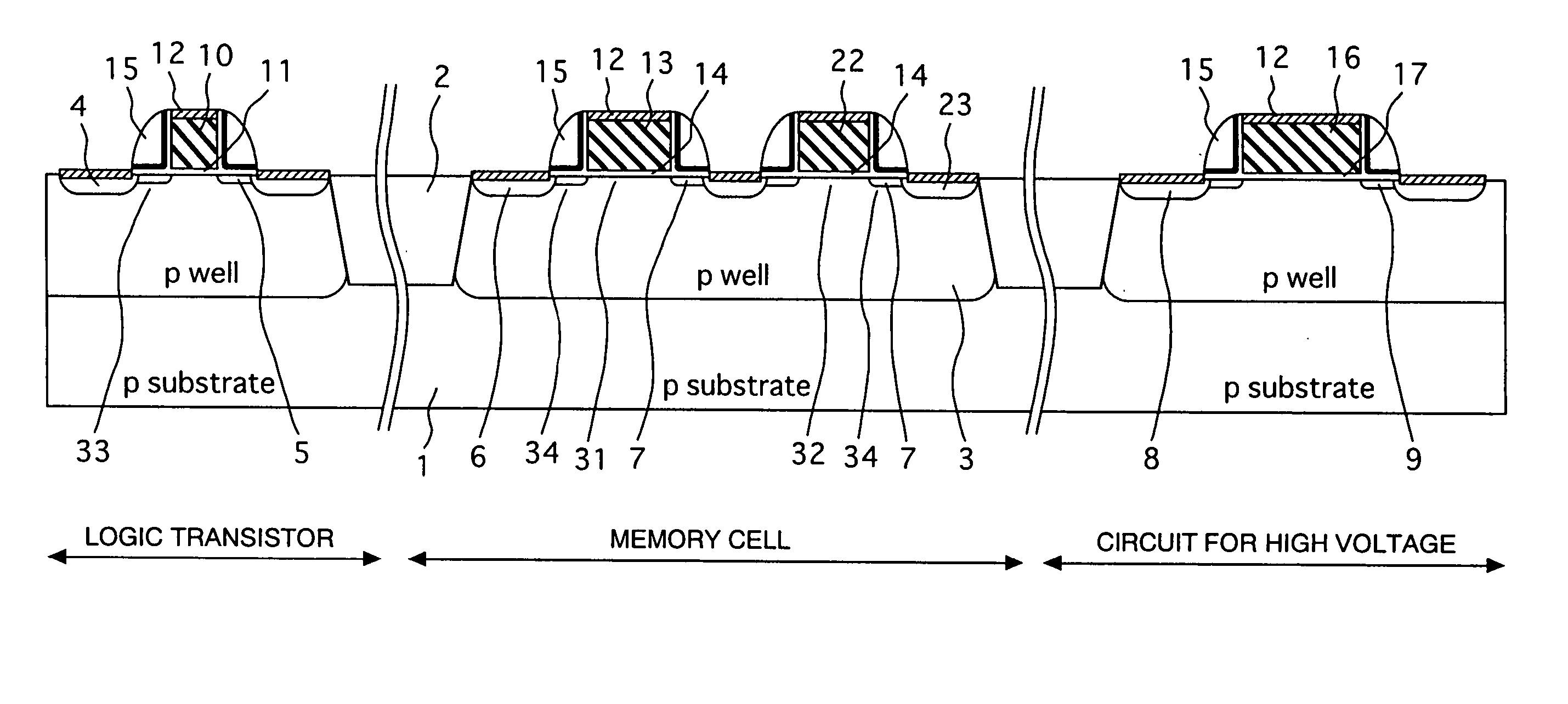
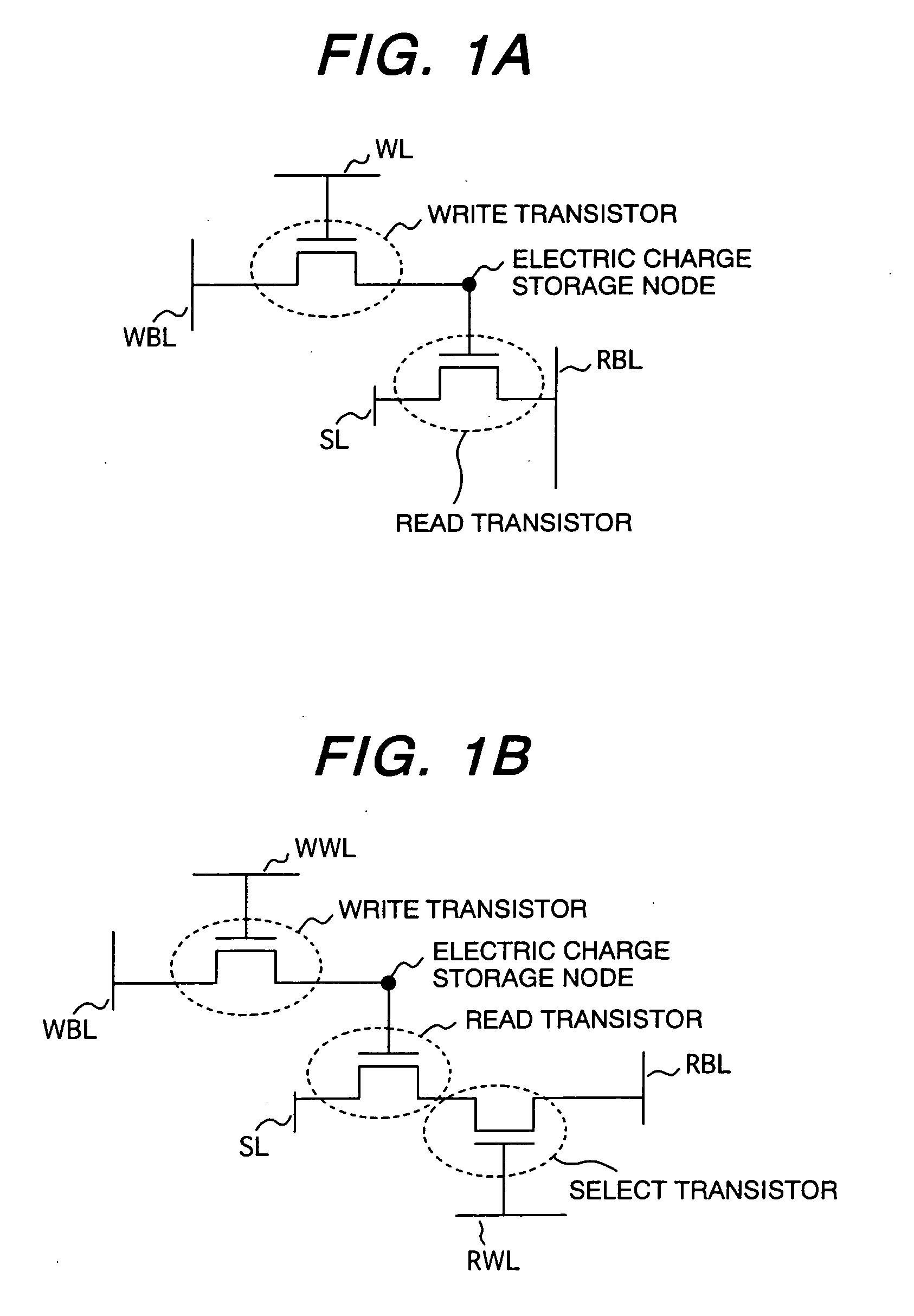
[0034]FIG. 3 is a sectional view showing in array form a logic transistor, a memory cell block, and a high-voltage transistor of a semiconductor chip according to a first embodiment. The memory cell block takes a three-transistor gain cell arrangement equivalent to that of FIG. 1B. FIG. 5 is a diagram showing a planar structure of the memory cell block. The memory cell block shown in section in FIG. 3 is equivalent to the section taken along line B-B of FIG. 5. A structure of the section taken along line A-A of FIG. 5 is shown in FIG. 4. FIGS. 6A and 6B are sectional views that explain manufacturing processes, and FIG. 7 is an equivalent circuit diagram explaining an array construction of the memory cell block. The portion boxed with a discontinuous line in FIG. 7 is equivalent to a unit memory cell. For the sake of convenience in description, the sectional views...

second embodiment

[0049]FIGS. 8 and 9 show a second embodiment of the present invention. FIG. 8 is a sectional view showing in arranged form a logic transistor, a memory cell block, and high-voltage transistor of a semiconductor chip according to the present embodiment. FIG. 9 is a top view of the memory cell block, section C-C of which is associated with a memory block of FIG. 8. In terms of equivalent circuit composition and operation, the present embodiment is the same as the first embodiment. Only differences between both embodiments are described below. The first difference exists in that a stereographic structure is employed for a write transistor. The present embodiment is characterized in that because of the stereographic structure being employed, the write transistor is formed directly above a read transistor and this arrangement results in a very small memory cell area. This write transistor of the stereographic structure has a channel film 21 made of the 3-nm-thick non-doped ultrathin amor...

third embodiment

[0052]FIG. 10 shows a third embodiment of the present invention. The present embodiment differs from the second embodiment only in the kinds of transistor-silicidizing material and write transistor-constituting materials. The differences from the second embodiment are described below. First, the present (third) embodiment uses nickel (Ni) as a silicidizing material. Except in special places, therefore, nickel silicide is present on a gate surface 12 and a diffusion layer surface. Nickel silicide has the features in which it is low in resistance compared with a cobalt silicide and enables uniform silicide patterns to be prepared even for fine gate electrode patterns. At the same time, however, it is also known that nickel silicide, because of its low thermal resistance, increases in resistance when qualitatively modified by annealing at about 600° C. Accordingly, if a transistor is processed using nickel silicide and then the write transistor structure as described in the second embo...


PUM


Abstract

The present invention is a semiconductor memory device having a logic block and a memory block on the same chip. In the memory device, unit memory cells each include at least two transistors, one of which is a write transistor for storing an electric charge into and releasing it from an electric charge storage node, and the other is a read transistor whose conductance in a channel region provided between a source and drain of the read transistor is modulated dependently on the amount of electric charge stored into or released from the electric charge storage node by the write transistor. The read transistor has a gate-insulating film thicker than that of a transistor provided in the logic block, and uses the same diffusion layer structure as that of the logic block.

Description

CLAIM OF PRIORITY [0001] The present application claims priority from Japanese application JP 2004-183338, filed on Jun. 22, 2004, the content of which is hereby incorporated by reference into this application. BACKGROUND OF THE INVENTION [0002] 1. Field of the Invention [0003] The present invention relates to semiconductor memory devices, and more particularly, to a semiconductor memory device that can simultaneously achieve both process consistency with logic transistors, and cost reduction. [0004] 2. Description of the Related Art [0005] With the progress of circuit pattern miniaturization, it has become possible to integrate a greater number of transistors on one chip and to endow the chip with a greater number of functions correspondingly. Compared with a processor / memory independent chip structure, on-chip memories each mounted together with a processor in mixed form on the same chip are superior in terms of both data transfer rate and electric power consumption. As mobile app...

Claims


Application Information

Patent Timeline
Patent Type & Authority Applications(United States)
IPC IPC(8): G11C11/405H01L21/8234H01L21/8239H01L27/105H01L27/11H01L29/10
CPCG11C11/405G11C2207/104H01L21/823456H01L27/1052H01L27/105H01L27/11H01L27/1116H01L21/823462H10B99/00H10B10/18H10B10/00
Inventor ISHII, TOMOYUKIMINE, TOSHIYUKISANO, TOSHIAKIKAMESHIRO, NORIFUMI
Owner RENESAS ELECTRONICS CORP
Why Eureka
Try Eureka