Universal fleecebacked roofing membrane

a technology of roofing membrane and fleece backing, which is applied in the field of roofing membranes, can solve the problems of no longer widely used roofing formulations, less resistance to cracking, and increased resistance to cracking, and achieves excellent weather resistance, good weather resistance, and non-flammability.

Inactive Publication Date: 2005-12-22
COOLEY
View PDF7 Cites 46 Cited by
  • Summary
  • Abstract
  • Description
  • Claims
  • Application Information

AI Technical Summary

Benefits of technology

[0009] The thermoplastic reinforced planar sheet is preferably comprised of a scrim or nonwoven coated fabric coated with a thermoplastic substrate, having good weather resistance. Exemplary of the thermoplastic substrate are thermoplastic polymers selected from the group consisting of ethylene-propylene-diene-monomer (EPDM), compounded PVC, elastomeric acrylic polymers, PVF (polyvinyl fluoride), elastomeric polyurethanes, chlorinated rubbers, elastomeric polyesters, modified bitumens, elastomeric polycarbonates, polyimides, polyamides, chlorosulfonated polyethylene, styrenated aliphatic block copolymers (e.g., Kraton® SEBS), modified elastomeric polyolefins, nitrile butyl rubber, silicone rubber, and blends thereof. A preferred thermoplastic substrate is a compounded PVC substrate. The PVC substrate is compounded to have excellent weather resistance and to be nonflammable. The PVC substrate can be applied as an emulsion, a sol, or extruded. An extruded compounded PVC substrate has processing characteristics that enable a substantial coating to be applied at relatively high manufacturing line speeds, and thereby lowering costs. The extruded PVC substrate has good thermal properties, good processability, good uniformity, and fungicidal and mold resistance. The preferred PVC resin is plasticized, for instance with a permanent plasticizer. Alkyl phthalates, and particularly diisodecyl phthalate (DIDP), epoxidized soybean oil, and ESO are commonly employed.
[0013] As previously stated, the thermoplastic reinforced planar sheet is needle punched forming a two-sided fleece. The fleece can be formed simultaneously on both sides of the thermoplastic reinforced planar sheet by needling a fibrous mat through the thermoplastic reinforced planar sheet, wherein fibers from the fibrous mat are needle punched through the planar sheet and to the opposing side. The needling process converts the thermoplastic reinforced planar sheet into a two-sided needle punched fleece, where the fibers project through the thermoplastic reinforced planar sheet. The first side of fleece and the second side of fleece are on opposing sides of the thermoplastic reinforced planar sheet. The thermoplastic reinforced planar sheet serves as a common supporting base for both sides of the fleece. The height of the pile is determined by the stroke length of the needling, less the thickness of the supporting base. An exemplary nominal range for the height of the pile is 0.4 mm to 5.0 mm. The nominal range of the base is 0.2 mm to 3.0 mm. The composition of the fleece is selected from the group consisting of: polyesters, nylons, polypropylenes, polyamides, polyimides, polyethylenes, cellulosic materials, glasses, polyacrylics, polycarbonates, polyacetals and ketals, polyurethanes, copolymers and terpolymers, and blends thereof. Polyester is particularly suitable as a fleece fiber for its combination of properties, including weather resistance, strength, availability and cost.
[0015] An additional desired criterion is that the thermoplastic polymeric layer also have good printability. Printability enables the creation of a roof membrane having various colors and designs. For instance, the disclosed invention can be coated or printed to have a helicopter target landing area, or colored to imitate a copper roof. The thermoplastic material is preferably applied as an extrudate onto one side of the fleece, such that the fleece fibers are intricately embedded in the thermoplastic polymeric layer. The process conditions can be adjusted to control the level of embedding.
[0021] Another object is to provide a roofing membrane that can be easily spliced using conventional PVC cements and thermal fusing techniques, such as RF welding.

Problems solved by technology

As such, they are subject to the problems caused by weather, worker error, and material inconsistencies.
Another potential thermoset material is neoprene, although this particular formulation is no longer widely used for roofing.
The polyester industry points out that fiberglass is inherently more friable, and the membrane will become hard and more subject to cracking.
More importantly, glass is hydrophilic and can cause water to weep into the membrane and, therefore, shortens the working life.
A problem with a continuous curing system is that there will be shrinkage as curing continues, however, and as the EPDM cures it becomes more difficult to splice, because it is difficult to adhere to, except at high temperatures.
A problem with a splice using a double-coated tape is that there will frequently be adjoining membranes that do no have a selvage width that can be co-joined, and tape will either have to adhere to the un-abraded side of the EPDM roofing membrane, or some fastening system, such as one that adheres to the fleece and the un-abraded side of the EPDM roofing membrane, will need to be employed.
In any case, the properties that contribute to the good weather resistance of EPDM rubber make splicing difficult.
RF welding or solvent etching, for instance, as is used to join thermoplastic materials is problematic because cement solvents tend not to dissolve, but just to swell the EPDM rubber.
Most EPDM membrane rubber is not thermoplastic, and does not facilely flow when heated, and has a low surface energy making EPDM rubber difficult to adhere to.

Method used


Image

  • Universal fleecebacked roofing membrane

Examples


Embodiment Construction

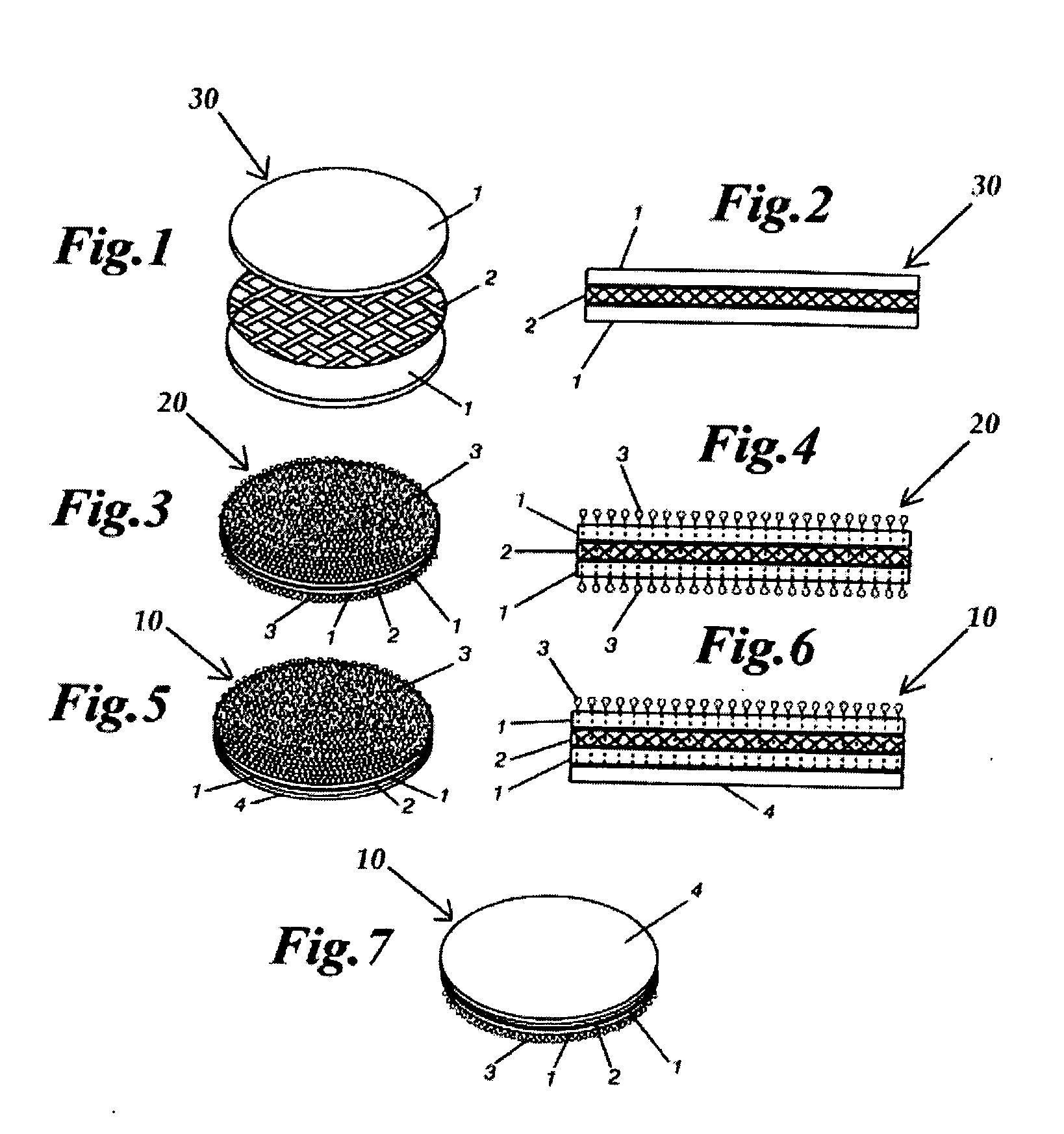
[0034] The invented product is a fleecebacked laminate that is suitable as a fleecebacked roofing membrane. The laminate is comprised of the following: 1) a thermoplastic reinforced planar sheet, 2) a needle punched fleece formed on both sides of the thermoplastic reinforced planar sheet, and 3) a thermoplastic polymeric layer extruded onto one side of the fleece. The fleece is formed by needle punching fibers through the reinforced planar sheet. The reinforced planar sheet serves as a common supporting base for the resulting two-side fleece. The thermoplastic polymeric layer is embedded with one side of the fleece fibers. The thermoplastic polymeric layer serves as the top layer of the roofing membrane, and the second side of fleece fibers serves as a felt. The thermoplastic polymeric layer is preferably composed of an extruded PVC substrate, compounded to have excellent weather resistance, printability, and to be nonflammable. The fleece fibers are preferably composed of polyester...


PUM

PropertyMeasurementUnit
thicknessesaaaaaaaaaa
heightaaaaaaaaaa
temperature performanceaaaaaaaaaa

Abstract

The invented product is a fleecebacked laminate that is suitable as a single-ply fleecebacked roofing membrane. The laminate consists of the following: 1) a thermoplastic reinforced planar sheet, 2) a needle punched fleece formed on both sides of the thermoplastic reinforced planar sheet, and 3) a thermoplastic polymeric layer extruded onto one side of the fleece. The fleece is formed by needle punching fibers through the reinforced planar sheet. The reinforced planar sheet serves as a common supporting base the resulting two-side fleece. The thermoplastic polymeric layer is embedded with one side of the fleece fibers. The thermoplastic polymeric layer serves as the top layer of the roofing membrane, and the second side of exposed fleece serves as a felt. The thermoplastic polymeric layer is preferably comprised of an extruded PVC substrate, compounded to have excellent weather resistance, printability and to be nonflammable. The fleece fibers are preferably composed of polyester. The thermoplastic reinforced planar sheet is preferably a scrim that is extrusion coated with a thermoplastic substrate that is compounded to have excellent weather resistance, and to be nonflammable.

Description

FIELD OF THE INVENTION [0001] The present invention relates generally to a roofing membrane, and more particularly to a roofing membrane having a fleece backing. BACKGROUND OF THE INVENTION [0002] Roofs having a single-ply roofing membranes are so named to contrast them with another group of commercial roofing products known as built-up roofing. Built-up roofs are literally constructed on the roof by the contractor using component materials such as felts and asphalt. As such, they are subject to the problems caused by weather, worker error, and material inconsistencies. Single-ply membranes, however, are flexible sheets of compounded synthetic materials that are manufactured in a factory to strict quality control requirements that minimize the risks inherent in built-up roof systems. Primary among the many physical and performance properties these materials provide are strength, flexibility, and long-lasting durability. The inherent advantages of pre-fabricated sheets are the consis...

Claims


Application Information

Patent Timeline
Patent Type & Authority Applications(United States)
IPC IPC(8): B32B3/16B32B5/26B32B27/04B32B27/12D04H13/00D06N3/06D06N7/00E04D5/10
CPCB32B27/12D04H13/002D06N5/00E04D5/10D06N2209/1692D06N3/06D04H11/08Y10T442/102Y10T442/159Y10T442/16Y10T442/164Y10T442/172Y10T442/174Y10T442/176Y10T442/178Y10T442/183Y10T442/50Y10T442/682B32B5/024B32B27/304B32B37/156B32B2262/0276B32B2305/026B32B2307/3065B32B2307/712B32B2398/20
Inventor MEHTA, NARESHFLATH, JEFFREY CHARLES
Owner COOLEY
Why Eureka
Try Eureka