Rotary machine and thermal cycle

a rotary machine and thermal cycle technology, applied in the field of rotary machines, can solve the problems of low efficiency of rotary power generation, and low technological advancement of internal combustion, and achieve the effect of minimal inertial loss

Inactive Publication Date: 2005-12-29
DUNCAN RONNIE J
View PDF9 Cites 6 Cited by
  • Summary
  • Abstract
  • Description
  • Claims
  • Application Information

AI Technical Summary

Benefits of technology

[0018] In accordance with yet other aspects of the invention, the toroidal housing prevents pressure loss due to cross leaking.
[0020] In accordance with still further aspects of the invention, the constant torque moment allows the rotary machine to operate at relatively low r.p.m. while achieving relatively high power output.
[0032] In accordance with yet other aspects of the invention, the combustion and expansion chambers are shaped to allow efficient expansion of combustion products with minimal inertial loss.

Problems solved by technology

However, despite its widespread use, the internal combustion, or Otto cycle, engine or, in certain instances, a diesel cycle engine, has received very little technological advancement.
The reciprocating motion of common internal combustion engines, Otto and diesel cycle, is an inefficient method of producing rotary power.
The reciprocating motion of the four-cylinder engine requires four inertial changes of the rotating mass of the pistons, connecting rods, and assembly—each change in inertia yielding a power loss to the system.
Likewise, each complete cycle of the internal combustion engine requires four inertial changes for the associated valves, springs, lifters, rocker arms, and push rods, yielding additional total loss of the engine.
The mechanical complexity of the standard internal combustion engine adds to the design's overall inefficiency.
Each one of these parts increases the probability of engine failure due to fatigue or wear.
Likewise, this large number of parts increases the amount of inertial mass that must change four times per cycle, reducing power produced by the system.
Each moving part is subject to frictional loss between each relative part, adding to power loss.
Further, it is expensive to manufacture and maintain equipment requiring such a large number of moving parts.
The resulting structural requirements limit piston assembly design, increasing mass and limiting material choice.
Further, transmissions are necessary to amplify the relatively low torque generated by the reciprocating motion, thus adding weight, cost, complexity and additional power requirements to the overall system.
The compression, and thus heating, of the original unit volume of combustion products leads to further power loss.
Likewise, the reciprocating design limits the combustion product's ability to do useful work because the expansion volume is not equal to the compression volume—combustion heats the gas, thus increasing the expansion volume beyond the initial volume.
Thus, relatively high-pressure combustion gases are exhausted without performing any useful work.
The overall design of Otto, diesel, and other rotary engines is limited by cross-leakage at high pressure.
More specifically, cross leaking is internal pressure loss due to overflow from the high-pressure side to the low-pressure side of the system while the pistons move throughout their stroke.
The excessive number of seals and connecting parts in other internal combustion engines creates cross-leakage liability.
Yet another limitation of current rotary engine technology is the internal combustion design of the engines.
The current designs fail to allow for use as external combustion or external detonation cycle engines.
A further limitation of current engine technology is a lack of design diversity.
The extent of diversity for typical internal engines is limited by a need to drive a common crankshaft from a plurality of reciprocating motions.
This limited design diversity prevents possible space-saving designs from being developed.
Another design limitation of the internal combustion engine is the singularity of its use.
Furthermore, the internal combustion engine itself is incapable of functioning as an air compressor, a vacuum pump, an external combustion engine, water pump, a drive turbine for expandable gas, or a drive turbine.

Method used


Image

  • Rotary machine and thermal cycle
  • Rotary machine and thermal cycle
  • Rotary machine and thermal cycle

Examples


Embodiment Construction

Physical Description

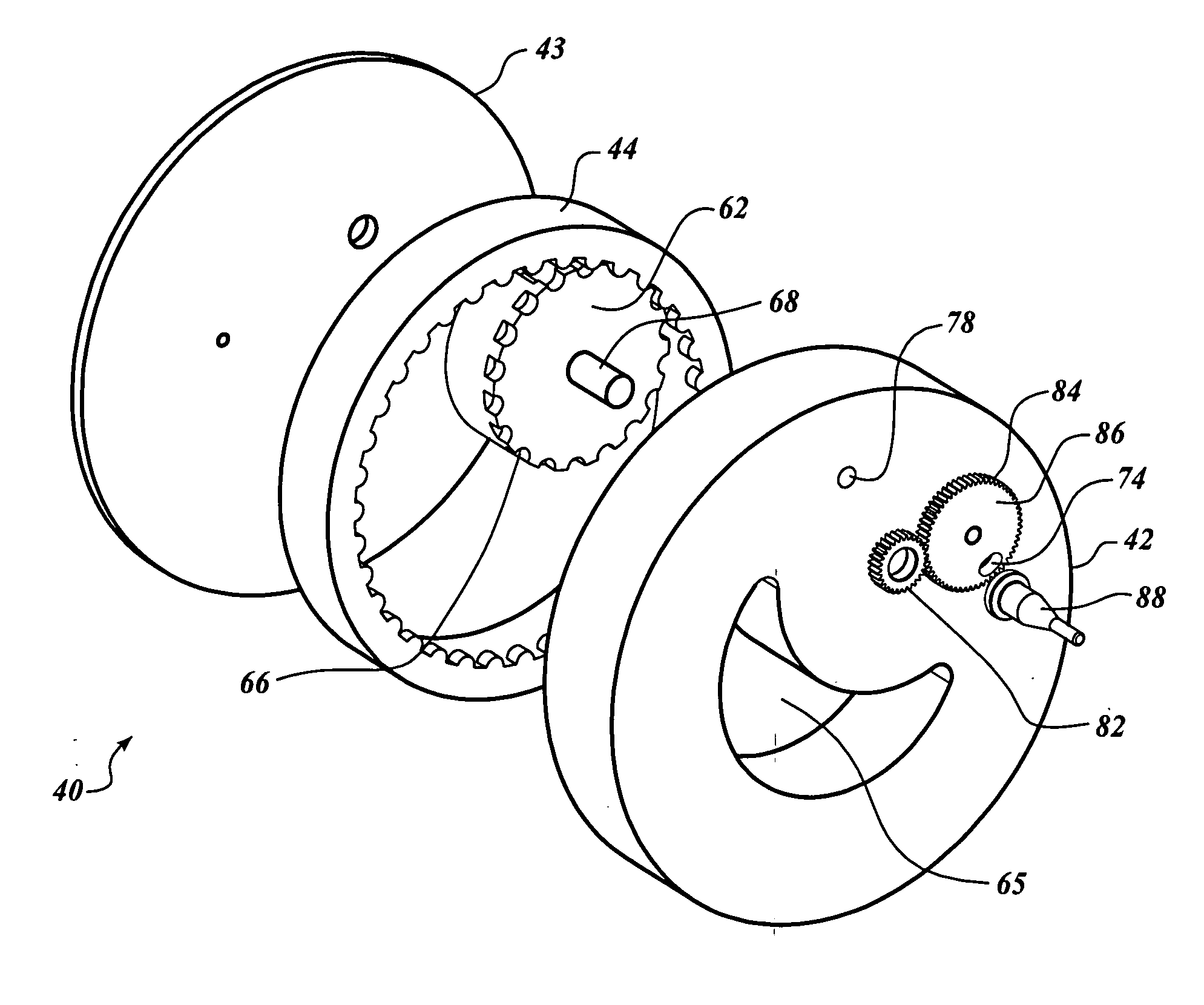
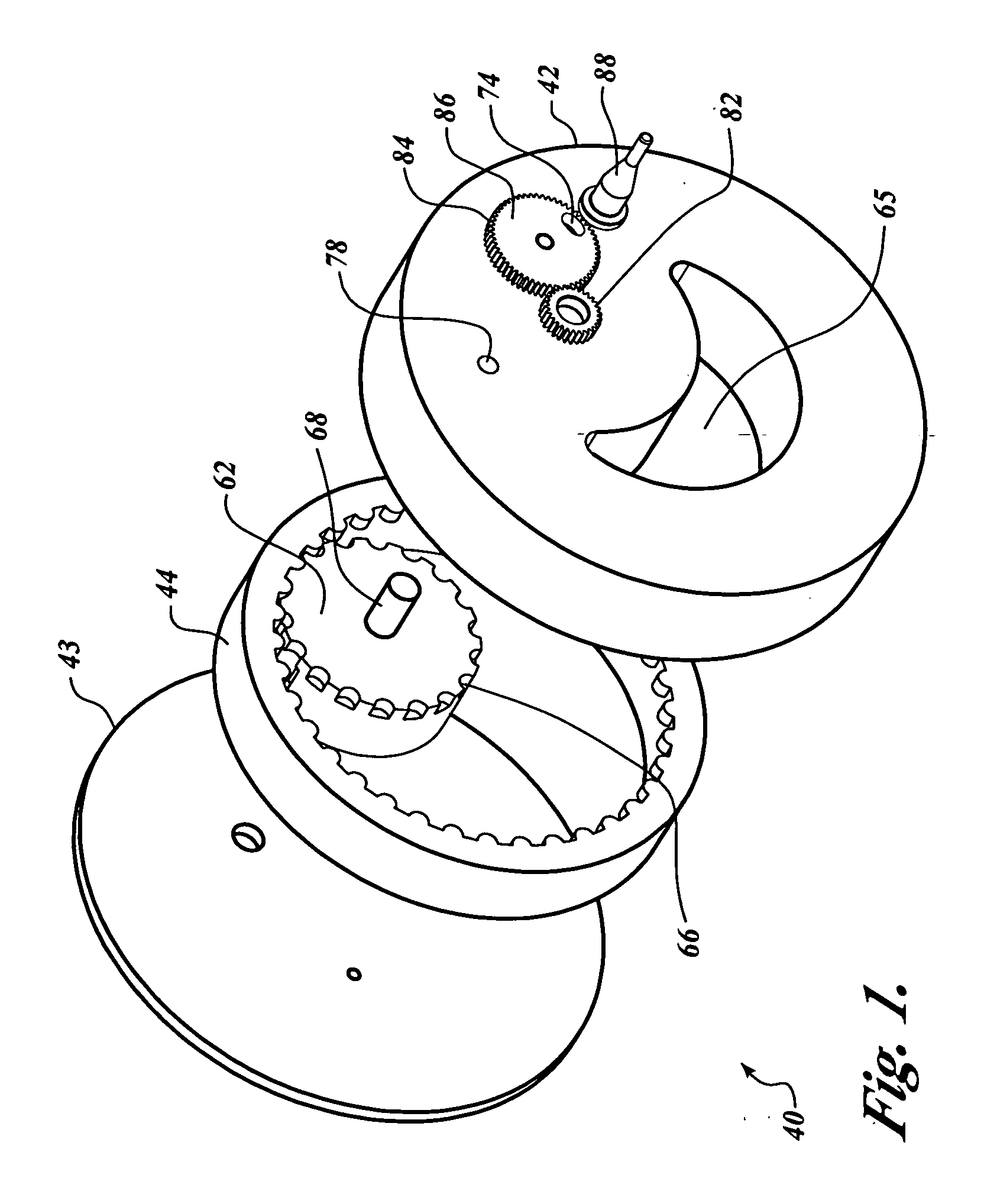
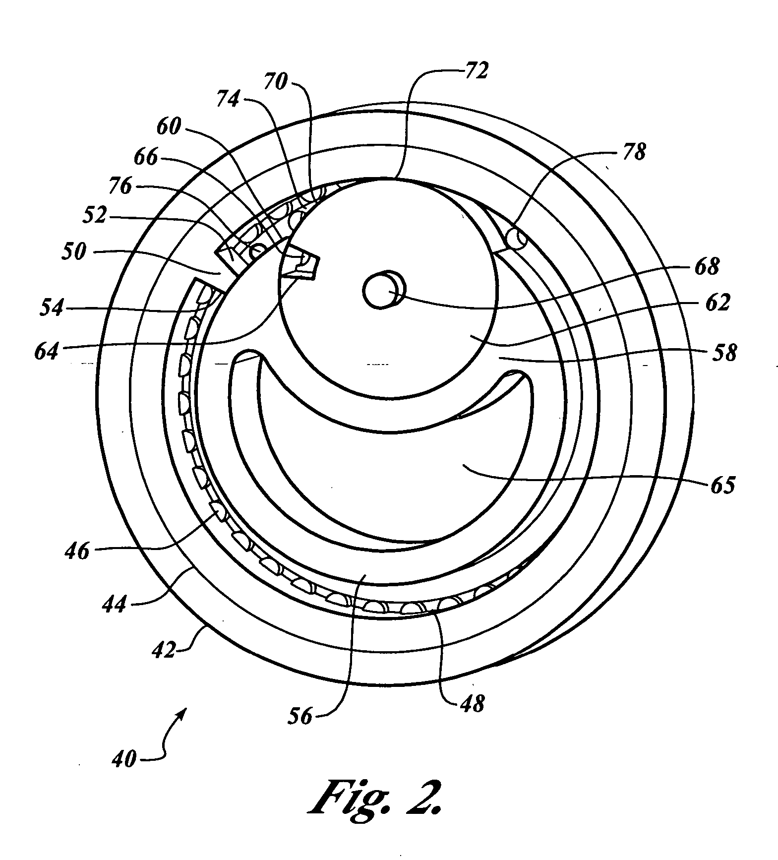
[0050]FIG. 1 depicts a preferred embodiment of a rotary machine 40. The rotary machine 40 employs a generally toroidal-shaped housing 42 having a cover 43 at one end. Disposed substantially within the toroidal housing 42 and integrally connected to the housing 42 is a plurality of rotary components. The generally toroidal-shaped housing 42 is substantially cylindrical in shape at its perimeter. However, at an end of the housing 42 opposite of the cover 43, the housing forms a generally toroidal inner housing 56 (see FIG. 2).

[0051] An expansion ring 44 is located within the housing 42 and the cover 43. More specifically, the expansion ring 44 is disposed between the toroidal housing 42 and the toroidal inner housing 56. The expansion ring 44 is generally cylindrical in shape, having disposed on a portion of its inner surface an expansion ring gear 46 (see FIG. 2). The expansion ring gear 46 and that corresponding portion of the expansion ring 44 are generally di...


PUM


Abstract

A rotary machine having a housing with rotary components disclosed within. The rotary machine is configurable as an internal combustion rotary engine, an external combustion rotary engine, a gas compressor, a vacuum pump, a liquid pump, a drive turbine, or a drive turbine for expandable gases or pressurized liquids. The combustion engine employs a new thermal cycle—eliminating the Otto cycle's internal compression of the combustion products as part of the cycle. The new combustion thermal cycle is intake, expansion and exhaust.

Description

PRIORITY CLAIM [0001] This application is a continuation of U.S. application Ser. No. 10 / 909,93. filed Jul. 30, 2004, which application is a continuation of U.S. application Ser. No. 10 / 261,174 filed Sep. 30, 2002, which claims priority to and is a divisional of U.S. application Ser. No. 09 / 850,937 filed May 7, 2001 (U.S. Pat. No. 6,484,687 issued Nov. 26, 2002). Each and all of the foregoing applications are incorporated by reference as if fully set forth herein.FIELD OF THE INVENTION [0002] This invention relates generally to rotary machines and more specifically to internal and external rotary combustion engines, fluid compressors, vacuum pumps, and drive turbines for expandable gases or pressurized fluid and water. BACKGROUND OF THE INVENTION [0003] As the human race has evolved throughout the centuries, we, as a people, have used our minds to develop machines and tools to help us achieve higher evolutionary standards. Technological advances include the invention and discovery o...

Claims


Application Information

Patent Timeline
Patent Type & Authority Applications(United States)
IPC IPC(8): F02B53/00F01C1/10F01C1/20F01C13/00
CPCF01C1/102F02B2053/005F01C1/20F02B53/00
Inventor DUNCAN, RONNIE J.
Owner DUNCAN RONNIE J
Why Eureka
Try Eureka